Building a berKEley
January 29, 2023
"What the hell is a Berkeley?" you ask.
That is the way it usually begins when I talk to someone unfamiliar with my infatuation with tiny sports cars made by the Berkeley Caravan company in Biggleswade England in the late 1950s.
I saw my first Berkeley around 1960 when my Uncle Fred brought one home. It was white and tiny and sounded and smoked like a small two stroke motorcycle. I knew nothing about cars at the time but I did know I liked this thing that looked like a slightly oversized kid's toy. Years passed and until the Internet made information about all things possible I had largely forgotten the Berkeley. But when I entered my retirement years I had a short list of cars I'd like to own some day, and one car on that list was a Berkeley.
I've learned that the winter months are when I surf the Internet and daydream about projects I'd like to be doing if it weren't so cold out. I've started several questionable projects that way and this winter it was a Berkeley. I casually reached out to a man known to own more Berkeley cars and parts than anyone in the USA. I was fully prepared to find the cost more than what it is worth to own a car that is too small to safely drive on any road with a speed limit higher than 25 MPH. But to my surprise he had exactly what I wanted at a price I couldn't refuse. I made up my mind while still on the phone and, with the help of my good friend David, drove six hours to pick up a trailer load of Berkeley parts to bring home and assemble.
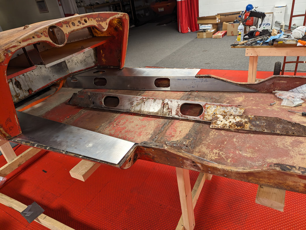
Here is a picture of the major components laid out on the floor of my garage. The large flat piece in the foreground is called the "punt" and is the fiberglass equivalent of a frame for a Berkeley. The rest of the car components sit on and bolt to it.
"What the hell is a Berkeley?" you ask.
That is the way it usually begins when I talk to someone unfamiliar with my infatuation with tiny sports cars made by the Berkeley Caravan company in Biggleswade England in the late 1950s.
I saw my first Berkeley around 1960 when my Uncle Fred brought one home. It was white and tiny and sounded and smoked like a small two stroke motorcycle. I knew nothing about cars at the time but I did know I liked this thing that looked like a slightly oversized kid's toy. Years passed and until the Internet made information about all things possible I had largely forgotten the Berkeley. But when I entered my retirement years I had a short list of cars I'd like to own some day, and one car on that list was a Berkeley.
I've learned that the winter months are when I surf the Internet and daydream about projects I'd like to be doing if it weren't so cold out. I've started several questionable projects that way and this winter it was a Berkeley. I casually reached out to a man known to own more Berkeley cars and parts than anyone in the USA. I was fully prepared to find the cost more than what it is worth to own a car that is too small to safely drive on any road with a speed limit higher than 25 MPH. But to my surprise he had exactly what I wanted at a price I couldn't refuse. I made up my mind while still on the phone and, with the help of my good friend David, drove six hours to pick up a trailer load of Berkeley parts to bring home and assemble.
Here is a picture of the major components laid out on the floor of my garage. The large flat piece in the foreground is called the "punt" and is the fiberglass equivalent of a frame for a Berkeley. The rest of the car components sit on and bolt to it.
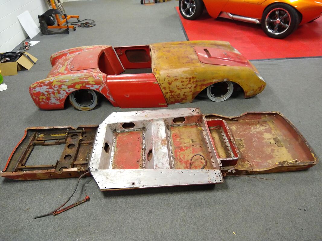
The Berkeley was designed by Lawrence Bond, the same man who designed the first Mini car. The fiberglass punt is reinforced with a steel subframe in the front for the engine, aluminum panels in the center for the cockpit and a very simple structure to support the independent rear suspension in the back. All Berkeleys were powered by air cooled motorcycle engines that drove the front wheels via a chain and sprocket system. Most models were designated based on the displacement size of their engines. My car started life as a 1958 SE 328 with a 328cc engine. The parts I purchased did not include the engine and some other incidental parts. That was fine with me as I have no intention of restoring the car to "like new" condition. I see my collection of Berkeley parts as the starting point for a hot rod whose character has not yet been finalized. All I know at this moment is that it will likely be powered by a motorcycle engine with forward and reverse gears.
February 11, 2023
I purchased my Berkeley in pieces from a man known to have more Berkeley car parts than anyone in the United States. Fortunately for me he is an honest man because I had no idea what parts I needed. After being sure I had the main body parts, I simply accepted the parts he gave me. Shortly after unloading everything at home I set about taking inventory of my haul. It turns out the Berkeley is a very simple car for a car guy like me to understand. I built a dolly to hold the punt at a comfortable level and began piecing together the suspension.
I'll note at this point that my overall plan is to piece the car together largely as is for my first step. This will reveal things that require repair, replacement or modification. When that is done and I know it works mechanically, I'll disassemble everything for cleaning, refinishing and final assembly.
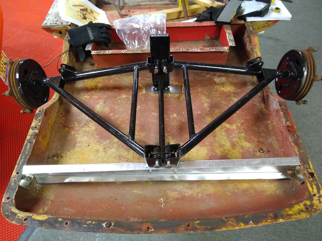
While sorting things out I discovered I had two of one part and none of another. The missing part is a bracket that ties the aft part of the rear suspension to the sides of the punt. It helps stabilize the aft mounting point of the independent rear suspension. From pictures I decided I could easily fabricate a replacement for the missing part from a sheet of 14 gauge aluminum. The new bracket is the wide aluminum piece in this photo.
February 11, 2023
I purchased my Berkeley in pieces from a man known to have more Berkeley car parts than anyone in the United States. Fortunately for me he is an honest man because I had no idea what parts I needed. After being sure I had the main body parts, I simply accepted the parts he gave me. Shortly after unloading everything at home I set about taking inventory of my haul. It turns out the Berkeley is a very simple car for a car guy like me to understand. I built a dolly to hold the punt at a comfortable level and began piecing together the suspension.
I'll note at this point that my overall plan is to piece the car together largely as is for my first step. This will reveal things that require repair, replacement or modification. When that is done and I know it works mechanically, I'll disassemble everything for cleaning, refinishing and final assembly.
While sorting things out I discovered I had two of one part and none of another. The missing part is a bracket that ties the aft part of the rear suspension to the sides of the punt. It helps stabilize the aft mounting point of the independent rear suspension. From pictures I decided I could easily fabricate a replacement for the missing part from a sheet of 14 gauge aluminum. The new bracket is the wide aluminum piece in this photo.
I've spent more time thinking about how to power the Berkeley than anything else. I've considered front and rear drives powered by gasoline, electric or a hybrid system. My choices are limited by budget, availability of original parts and the technical challenges of adapting such a strange little car to modern technology. I keep coming back to the idea of using as much of the original car as possible while adapting a new engine to fit in the engine compartment. My research indicates that is the best path forward provided I can obtain an original chain drive differential for the front. My friend Kevin Kalman is looking to see if he has one in his stash of parts. Until I hear back from him, all I can do is wait.
October 16, 2023
Progress has been slow due to parts availability, me working out how to fit things together, and life getting in the way. But the chain differential did arrive as did parts for a new axle and brake assembly for the rear suspension. I was also able to assemble a prototype front hub and CV axle using parts of a Suzuki ATV. This approach allows me to avoid having to obtain hard-to-find brake parts from an original Berkeley. The price for this approach is sourcing difficult-to-find wheels and tires that will fit the both the ATV hub bolt pattern and the small space in the Berkely fender wells. They are currently on order from a supplier in Japan.
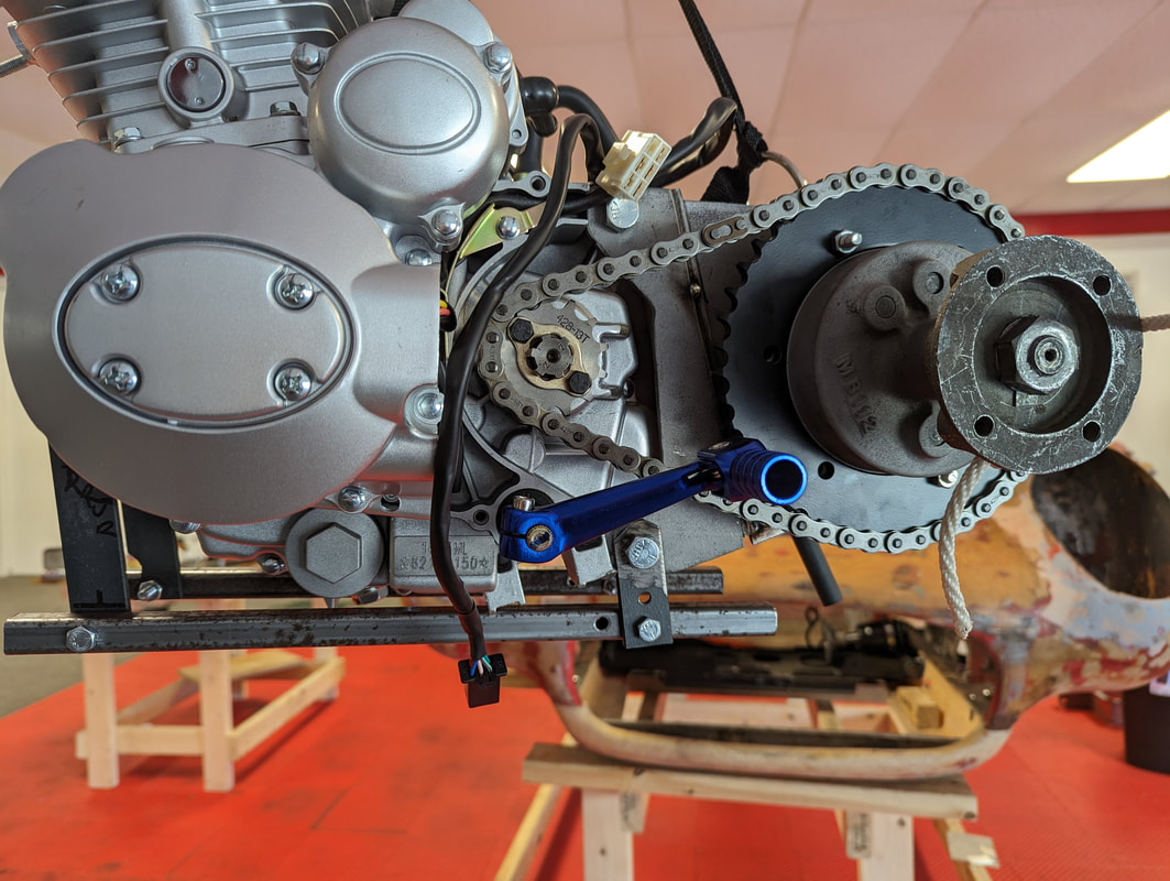
One of the challenges I'm still working illustrates why this project is taking so long. This involves making a bracket to connect the differential to the engine. This picture of someone else's modified Berkeley shows how the bracket aligns and supports the differential while providing a means for tension the chain.
October 16, 2023
Progress has been slow due to parts availability, me working out how to fit things together, and life getting in the way. But the chain differential did arrive as did parts for a new axle and brake assembly for the rear suspension. I was also able to assemble a prototype front hub and CV axle using parts of a Suzuki ATV. This approach allows me to avoid having to obtain hard-to-find brake parts from an original Berkeley. The price for this approach is sourcing difficult-to-find wheels and tires that will fit the both the ATV hub bolt pattern and the small space in the Berkely fender wells. They are currently on order from a supplier in Japan.
One of the challenges I'm still working illustrates why this project is taking so long. This involves making a bracket to connect the differential to the engine. This picture of someone else's modified Berkeley shows how the bracket aligns and supports the differential while providing a means for tension the chain.
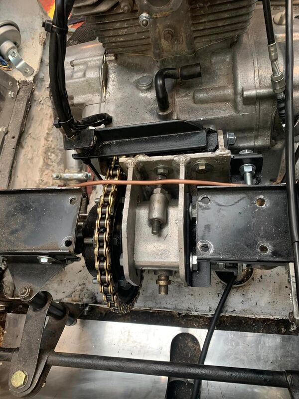
Just to the right of the chain you see an aluminum bearing housing sandwiched between two metal plates that are part of the bracket securing the differential to the engine. To begin work on my bracket I had to first disassemble the differential assembly to be able to access both side of the bearing housing that supports the inboard ends of the CV axles. My differential was very old and appeared to have been without lubrication for a long time. With advice from people in the Berkeley community I was able to open it up without damaging anything. Inside I found it was a "spur gear differential."
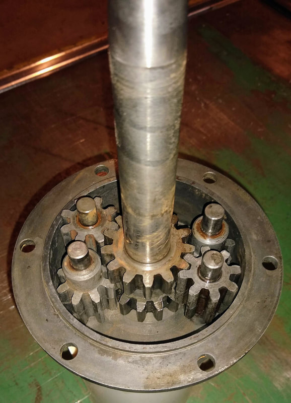
Inside the case axles from each side have gears that mesh with four small spur gears to produce the differential effect. The gears in my case were immovable due to age do I soaked them in penetrating oil followed by a rust remover to free them up. While I had not intended to rebuild the entire differential at this stage of the project, I decided to go ahead and replace the bearings and seals in the bearing housing while it was apart. I was able to locate replacement parts through the Berkeley Enthusiasts Club (BEC) based in England. At this moment I am still waiting for those parts to arrive.
November 14, 2023
New bearings arrived from England and I continued my disassembly of the differential. It turned out each of the spur gears is supposed to rotate on its center shaft and all four were frozen tight. Days of soaking them in my homemade penetrating oil solution loosened them up. I was also able to remove both old bearings to have the entire differential apart and ready for cleaning.
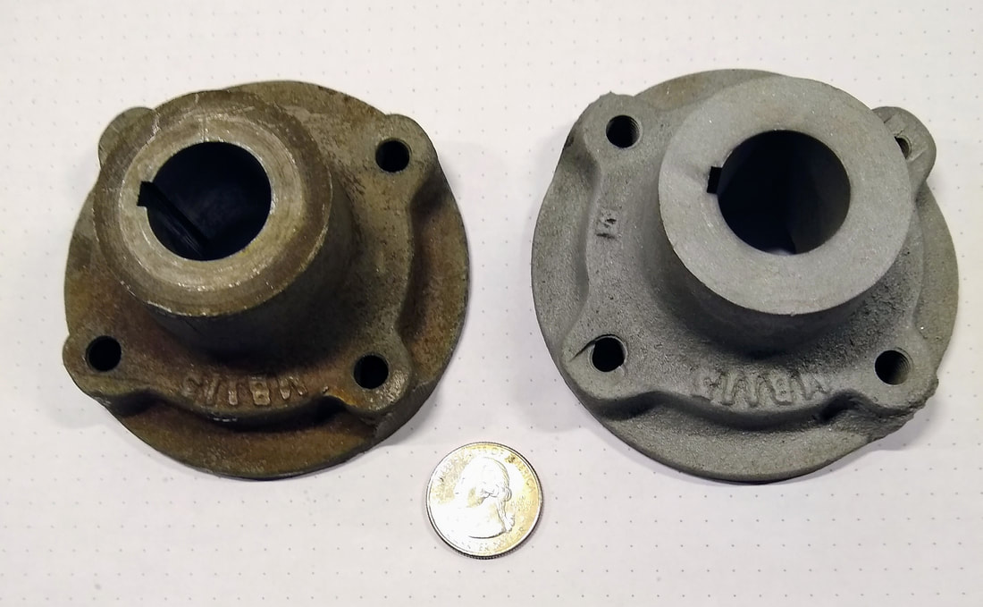
Seeing all the old, dirty parts of the Berkeley that need attention I decided to add a media blasting cabinet to my shop. I spent a week assembling and modifying an inexpensive Harbor Freight piece to meet my needs. With some tweaks, it is working well. Here's a picture of parts before and after about one minute of blasting.
November 14, 2023
New bearings arrived from England and I continued my disassembly of the differential. It turned out each of the spur gears is supposed to rotate on its center shaft and all four were frozen tight. Days of soaking them in my homemade penetrating oil solution loosened them up. I was also able to remove both old bearings to have the entire differential apart and ready for cleaning.
Seeing all the old, dirty parts of the Berkeley that need attention I decided to add a media blasting cabinet to my shop. I spent a week assembling and modifying an inexpensive Harbor Freight piece to meet my needs. With some tweaks, it is working well. Here's a picture of parts before and after about one minute of blasting.
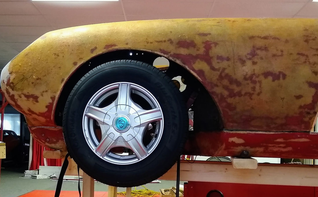
One task that took a long time to complete was choosing wheels and tires for the Berkeley. Due to my earlier decision to use the front hubs from a Suzuki Eiger ATV, I was faced with finding wheels and tires with very specific and hard-to-find characteristics. Here are the characteristics needed:
- Tires about 21.5 inches tall and 5 to 6 inches wide
- Wheel bolt patterns matching the ATV (4 bolts on a 110mm circle)
- A center hole compatible with front and rear hubs
- Enough room on the backside of the wheel for front and rear disc brake calipers
- Correct wheel width and backspacing to fill the wheel wells without touching the body
- Wheels and tires currently available for a tolerable price (including shipping)
March 10, 2024
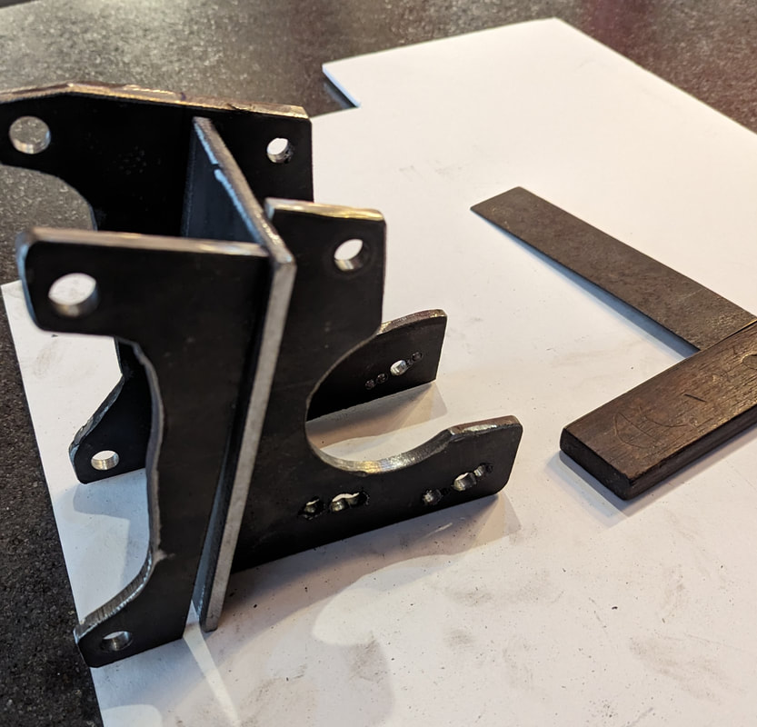
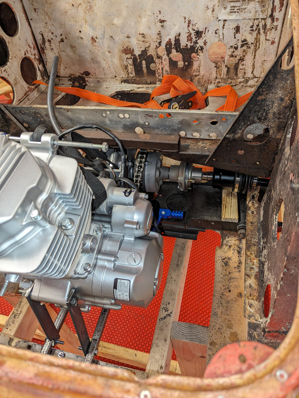
Progress on the Berkeley picked up over the past month. The first major accomplishment was completing the refresh of the differential and fabricating a bracket to attach it to the engine. Here are photos of the complete (but not finish welded) bracket, the complete engine/differential assembly and the engine hanging in the engine compartment for a test fit.
Progress on the Berkeley picked up over the past month. The first major accomplishment was completing the refresh of the differential and fabricating a bracket to attach it to the engine. Here are photos of the complete (but not finish welded) bracket, the complete engine/differential assembly and the engine hanging in the engine compartment for a test fit.
The test fit showed that the engine assembly will fit. The next challenge was to decide how to mount the engine assembly in the car. This picture and brief description should make it easy to understand. The old engine supports consist of four steel pieces. The rear engine support is the heaviest of them and ties the front suspension to the engine and body. Essentially the front wheels and suspension support the engine and front of the body. The front engine support connects to the fiberglass punt. The two longitudinal pieces connect the front and rear engine supports.
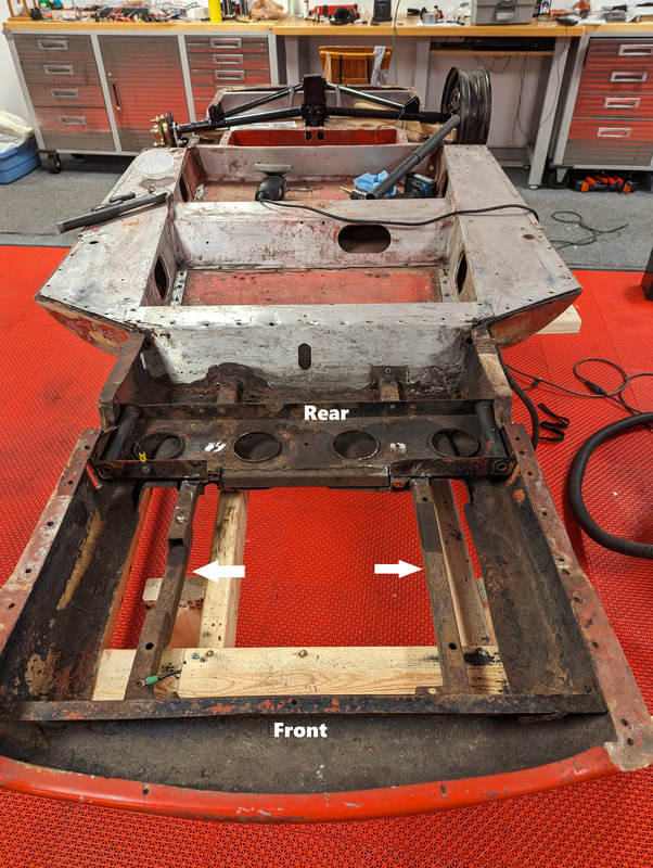
In this case the rear engine support and both longitudinal supports had been heavily modified by a previous owner, presumably to allow installation of a non-stock engine. The mods were rusted, very rough and not suitable for my plans, so I removed all four pieces. Fortunately I have a replacement for the rear support and the front support looks to be useable.
Removing the rear engine support turned out to be a much bigger job than I anticipated. It turns out that piece was slid into place before much of the aluminum pieces in the center of the punt were installed. So to remove it I had to first remove the footwell crossover piece. All together this step required the removal of about a dozen rusty 65 year old bolts and about five dozen tough stainless steel rivets. It was not fun. After several days it looked like this, and cleaning it all up is the next major step.
Removing the rear engine support turned out to be a much bigger job than I anticipated. It turns out that piece was slid into place before much of the aluminum pieces in the center of the punt were installed. So to remove it I had to first remove the footwell crossover piece. All together this step required the removal of about a dozen rusty 65 year old bolts and about five dozen tough stainless steel rivets. It was not fun. After several days it looked like this, and cleaning it all up is the next major step.
Cleaning up the punt began with research on the best way to do it without leaving residue in the fiberglass that would make repainting difficult. In the end I decided t that media blasting would be best, so I decided to first remove the metal pieces. That will also make it easier to repair some of the damage done to the metal by a previous owner. it was never my goal to do a proper stock restoration, but items have to be repaired just to assure the car is structurally sound.
As an aside I noted that the rectangular raised metal piece to the left of the aluminum pieces is not stock. It serves as the base support for the seats and as it seems structurally sound, I may reuse it after it is cleaned up.
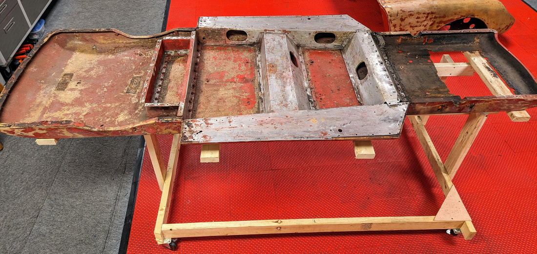
March 18, 2024
This photo shows the punt after the engine area was blasted clean. Cleaning was necessary both for painting in the future and to facilitate closing the large hole with new fiberglass. I chose to not do the rest as it will not be seen in the final build.
As an aside I noted that the rectangular raised metal piece to the left of the aluminum pieces is not stock. It serves as the base support for the seats and as it seems structurally sound, I may reuse it after it is cleaned up.
March 18, 2024
This photo shows the punt after the engine area was blasted clean. Cleaning was necessary both for painting in the future and to facilitate closing the large hole with new fiberglass. I chose to not do the rest as it will not be seen in the final build.
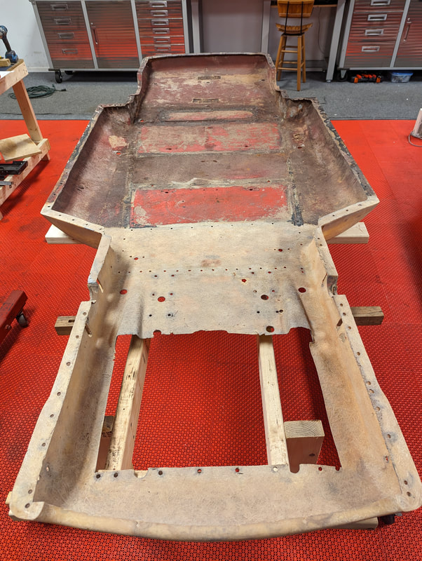
March 27, 2024
The two previous pictures show the punt, first with the old metal reinforcing pieces and then with them removed. I decided to replace most of those pieces with new ones I fabricated. Those pieces will not be visible in the finished car. but the old ones had areas of deep corrosion and many of the rivet mounting holes had been grossly enlarged when a previous owner apparently pulled pieces apart by force rather than removing the many rivets. Using the old pieces as patterns I made two large aluminum sill pieces and two steel reinforcing pieces that go just forward of the rear wheels. This picture shows the new pieces laid roughly in place and some old pieces in the center of the punt for comparison.
The two previous pictures show the punt, first with the old metal reinforcing pieces and then with them removed. I decided to replace most of those pieces with new ones I fabricated. Those pieces will not be visible in the finished car. but the old ones had areas of deep corrosion and many of the rivet mounting holes had been grossly enlarged when a previous owner apparently pulled pieces apart by force rather than removing the many rivets. Using the old pieces as patterns I made two large aluminum sill pieces and two steel reinforcing pieces that go just forward of the rear wheels. This picture shows the new pieces laid roughly in place and some old pieces in the center of the punt for comparison.
April 11, 2024
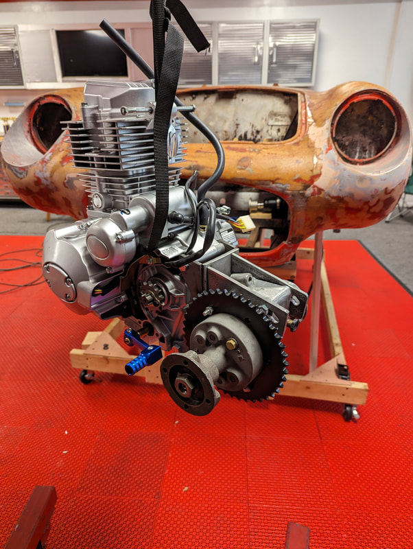
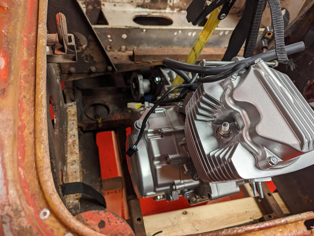
With the engine compartment cleaned up I started the task of fitting the engine into the car. As the car is mostly fiberglass, most of the weight of the engine is supported by a reinforced steel crossmember that goes from side to side between the two front wheel. The crossmember is connected to the front suspension control arms at each side so the wheels support the suspension that support the crossmember that supports the engine/differential. There is a much lighter formed steel piece that goes from side to side at the very front of the punt. These two steel pieces provide support for longitudinal steel pieces that are positioned to support the engine. The following three pictures show the engine bolted to the longitudinal supports and the engine in the car with the hood placed to check for clearance.
With the engine compartment cleaned up I started the task of fitting the engine into the car. As the car is mostly fiberglass, most of the weight of the engine is supported by a reinforced steel crossmember that goes from side to side between the two front wheel. The crossmember is connected to the front suspension control arms at each side so the wheels support the suspension that support the crossmember that supports the engine/differential. There is a much lighter formed steel piece that goes from side to side at the very front of the punt. These two steel pieces provide support for longitudinal steel pieces that are positioned to support the engine. The following three pictures show the engine bolted to the longitudinal supports and the engine in the car with the hood placed to check for clearance.
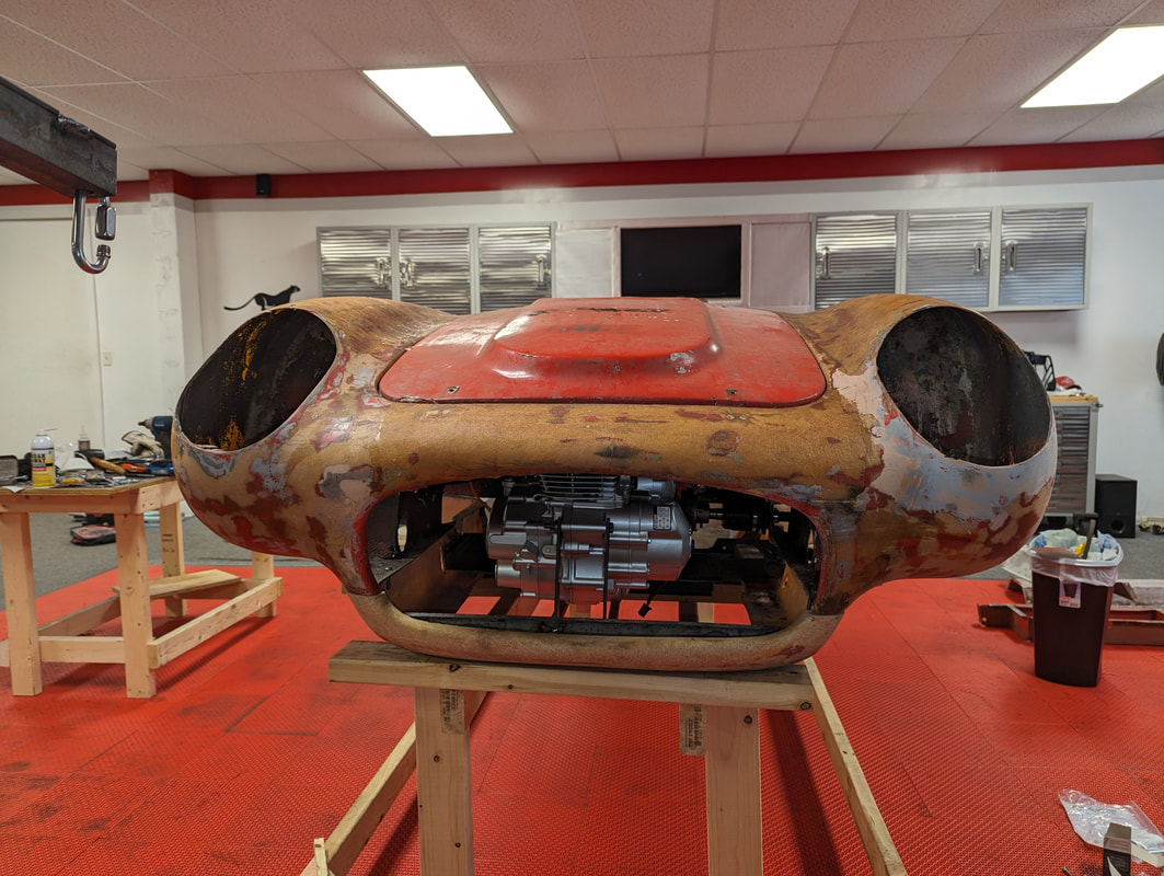
The engine support system is a prototype with lots of holes to allow different engine placements. I changed them about five times before I was satisfied. When I am confident it is correct, I'll remake it with welded and reinforced pieces. . . . You may have noticed that the nose of the car is resting on the punt. That was necessary to assure the differential cleared a portion of the nose that sits directly above it. There is only about 3/4 inch between obstructions above and below when the differential is properly positioned between the two front CV axles.
Fitting the engine was only the first step in assuring that everything else will have a place under the hood. And the one thing that will occupy the most space might be my favorite part of the engine. Some time ago I decided that a single cylinder 200cc engine might be the right thing for a car that will only be used at car gatherings, but I wanted to give a bit more personality. So I decided to turbocharge it with the smallest turbocharger currently for sale on the Internet. My guess is that it may add as much as 25% to the engine's peak power, or a whopping 4 HP! Here's what it looks like sitting next to a ubiquitous Harbor Freight free flashlight.
Fitting the engine was only the first step in assuring that everything else will have a place under the hood. And the one thing that will occupy the most space might be my favorite part of the engine. Some time ago I decided that a single cylinder 200cc engine might be the right thing for a car that will only be used at car gatherings, but I wanted to give a bit more personality. So I decided to turbocharge it with the smallest turbocharger currently for sale on the Internet. My guess is that it may add as much as 25% to the engine's peak power, or a whopping 4 HP! Here's what it looks like sitting next to a ubiquitous Harbor Freight free flashlight.
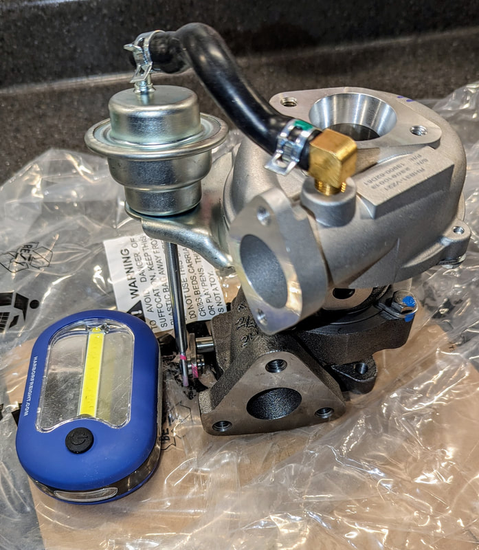
This thing is very compact but demands a lot of knowledge, preplanning and plumbing. As I knew virtually nothing about turbochargers I spent a lot of time learning about them. And I learned that many of them fail very early on mostly due to oil leaks. I'll digress here for a moment to share the main points I think apply. First, as turbos spin at speeds upward of 100,000 RPM, they need oil to lubricate their bearings. Second, at those speeds and temperatures there are no seals (e.g., rubber or silicone) that can survive, so a turbo does not have seals. Rather it has pieces near the ends of the central rotating shaft that throw oil back away from the hole in which the shaft is turning. Thus, if the volume of oil inside the bearing housing gets too high, the turbo will begin to leak. To prevent this the drain fitting at the bottom of the turbo housing is quite large to allow excess oil to gravity drain back to the engine crankcase. It is my understanding that the main reason some turbochargers like mine have leaked is because they were incorrectly installed such that oil was allowed to pool in the housing.
As long as I'm speaking of the oiling system I'll note that it is one of three plumbing systems that have to be sorted out. The one in my Berkeley will take pressurized oil from the head cover of the engine and route that through a small oil cooler. Oil on the way back to the head cover will pass through a T-fitting to syphon off enough oil for the turbocharger. Oil departing the turbocharger will drain back to the engine crankcase via a fitting in the oil filter cap.
The second plumbing system is for the engine exhaust that powers the turbocharger. I am fabricating a custom exhaust pipe to connect the two. After passing through the turbine the exhaust will exit through another custom pipe out the bottom of the engine compartment. I don't yet know if I will need a muffler.
The third plumbing system is for the air passing through the turbocharger compressor on its way to the engine intake. There are two ways to position the carburetor when a turbocharger is used. The draw through configuration positions the carburetor before the compressor and it requires no special modification to work. The compressed carburetor configuration places the carburetor downstream from the compressor and exposes the entire carburetor to increase ambient air pressure making it technically challenging to get the air/fuel ratio correct. As peak performance was not my goal, I decided to use the draw through configuration. That required me to acquire the pieces needed to attach the carburetor to the compressor intake, and to connect the compressor output to the engine intake.
April 30, 2024
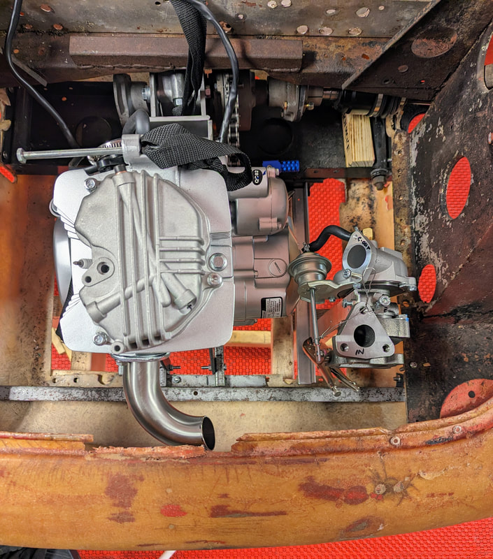
My first step toward installing the turbocharger was deciding where and how to mount it. I decided to place it on the driver side of the engine as it looks to be easier to plumb the exhaust and intake from there. This photo from directly above while standing at the front shows the turbo and the first bit of exhaust tubing. My plan is to sort out the ends of the exhaust pipe first, and then figure out how to connect those two pieces together.
As long as I'm speaking of the oiling system I'll note that it is one of three plumbing systems that have to be sorted out. The one in my Berkeley will take pressurized oil from the head cover of the engine and route that through a small oil cooler. Oil on the way back to the head cover will pass through a T-fitting to syphon off enough oil for the turbocharger. Oil departing the turbocharger will drain back to the engine crankcase via a fitting in the oil filter cap.
The second plumbing system is for the engine exhaust that powers the turbocharger. I am fabricating a custom exhaust pipe to connect the two. After passing through the turbine the exhaust will exit through another custom pipe out the bottom of the engine compartment. I don't yet know if I will need a muffler.
The third plumbing system is for the air passing through the turbocharger compressor on its way to the engine intake. There are two ways to position the carburetor when a turbocharger is used. The draw through configuration positions the carburetor before the compressor and it requires no special modification to work. The compressed carburetor configuration places the carburetor downstream from the compressor and exposes the entire carburetor to increase ambient air pressure making it technically challenging to get the air/fuel ratio correct. As peak performance was not my goal, I decided to use the draw through configuration. That required me to acquire the pieces needed to attach the carburetor to the compressor intake, and to connect the compressor output to the engine intake.
April 30, 2024
My first step toward installing the turbocharger was deciding where and how to mount it. I decided to place it on the driver side of the engine as it looks to be easier to plumb the exhaust and intake from there. This photo from directly above while standing at the front shows the turbo and the first bit of exhaust tubing. My plan is to sort out the ends of the exhaust pipe first, and then figure out how to connect those two pieces together.
At this stage I realized that fitting the exhaust system pieces would require them to be cut and fit very precisely so they could be welded together. For that reason I decided to replace the temporary engine support pieces with the permanent ones to assure everything would be in its proper place. So I removed the nose of the car, the engine and the support pieces. I also decided I would need to replace the front horizontal support piece so it could hold the longitudinal piece that will support the weight of the turbo. It is just a single sheet of steel with two bends in it, so it was not a difficult fabrication job. It attaches to the punt with rivets, but I will need the holes in new places to accommodate new engine mount system. So while I had it out I began filling all the old holes so I could put new ones wherever needed.
