April 7, 2015
I was inspired to create this website by the impending start of my next big project, building a tribute Cheetah. But before I can start on the project, I must first pick it up and bring it home. So it seemed right to begin this slightly off topic portion of the website with some words about the challenge of retrieving this kit from its current owner in Minnesota.
I have been searching the Internet for the right kit at the right price anywhere in the USA for the past five years. So, while discovering it in Minnesota was not a good as say finding it in Mississippi, it was still well within the distance I was willing to travel. But it is still a long way from Alabama to Minnesota. In addition, I have decided to take a detour on the way home to visit the man who builds the car components and will likely provide additional components and help as the project moves forward. His shop is in Ohio. All in all, I expect the trip to cover 2,800 miles and take about five days.
There was a time when a trip of that distance was mostly about finding a good audio book to help pass the time. But I admit that I'm getting older and driving for long stretches is a lot more uncomfortable now than in past years. So I decided to invite two of my best friends to come along to keep me company and share the driving duties. My nephew Bill was able to work it into his schedule and we plan to hit the road on April 22. I am most grateful for him taking time to help me with this.
With the itinerary and travel party set, I decided the time had come to replace my old pickup truck with a newer one. I could never convince myself to take a good friend on a trip in a truck with nearly 300,000 miles on it. So I got a 2014 Ford F-150 with an EcoBoost engine. So far, I like it a lot.
The one other thing I would need was a trailer to carry the Cheetah back home. After considering lots of options, I decided to build my own custom trailer starting with a stripped former boat trailer I found on craigslist. It was the right size, the right weight capacity, the right price and was a blank canvas for what I had in mind. ... Working with the car dimensions, I built a deck, complete with fenders, a winch mount and tie downs.
April 22, 2015
Bill and I hit the road around sunrise and headed north. He was great company and provided welcome relief from driving. We noted trees that had already bloomed in Alabama at earlier stages of their Spring development as we went farther north. It was like we were turning back the clock on Spring. The world didn't look profoundly different until we neared Iowa. The farms there go from horizon to horizon and are marked by perfect looking fields and picture book farm houses far back from the highway. We spend the night in Iowa City, Iowa.
April 23, 2015
We got off to an early start and arrived at Don Atkinson's home near Minneapolis, MN midday. Don was storing the car for his brother, Mark. Mark and I closed the deal and we loaded the car into the trailer. It fit like a glove. Mark and Don were very nice people and plainly car guys like us. Don showed us his Cobra replica that had been sharing space with the Cheetah. With all the parts loaded, we headed on to La Crosse, WI for the night. Bill paid me the $1 he lost when neither Mark or Don mentioned Alabama football. In his experience, people up north immediately associated people from Alabama with the UA football program. Apparently college football is not as much of a year round obsession in Minnesota.
April 24, 2015
To get to Ohio from Minneapolis, we had to drop down enough to get below the Great Lakes and go east toward Cleveland, OH. It was a full day's drive with traffic and road construction near Chicago making it harder. The worst part of that day was paying tolls every 15-20 minutes. I estimate I paid $75 in tolls in Illinois and Ohio. The coolest thing I saw was where the Interstate crossed Thornton Quarry. The bridge is 400' above the floor of the quarry and it feels like you are suspended in midair. Google it for pictures.
April 25, 2015
Bill and I visited the Cheetah shop the next morning. They showed us a nearly completed car they are assembling for a customer. Each of their cars (and each of the Cheetah's ever built) is custom in some way. No two are exactly alike. This history encourages me to build my car the way I want without being constrained by history. There were bits and pieces of the car that I liked and that I didn't like. But overall, it was a beautiful machine that sounded very intimidating when the engine started. It was very helpful to see it in person.
After an hour, Bill and I said goodbye and headed south. Our plan was to make it to Knoxville, TN for the night. On the way we realized we could make it all the way home before it got too late. The weather and traffic cleared and we pressed on. I arrive home around 10:30 PM and Bill about 45 minutes later. I had traveled more than 2,800 miles in four days and Bill topped me with about 2,900 miles. It was good to be home.
April 28, 2015
It has been my inclination from the beginning of the Cheetah project to have it powered by a traditional looking small block Chevy engine. I wanted it to resemble the 1963 Corvette engines used in the originals.
As I dug deeper into what made those engines look the way they did, I discovered that a key element was the valve covers. The iconic finned aluminum valve covers with Corvette written in script had no oil fill or breather holes in them. Later engines do have holes in the valve covers. The early engines didn't need them because the oil fill was in the intake manifold, and the breather tube was mounted in a hole in the block. More recent engine blocks do not have this hole. So to get the look I want, I will likely have an engine custom built with an intake manifold equipped with an oil fill breather and modified to accept a PCV valve.
May 2, 2015
I decided the first step on this long project was building a wooden jig to hold the fiberglass body until it is needed. The body is very light, but not thick enough to support its own weight without flexing. The jig should help it hold its shape while it sits.
The second step was mounting the suspension so the chassis can be on wheels and at something approaching ride height. That meant the 25 year old Corvette suspension pieces needed to be overhauled. In addition, I determined the differential that came with the kit was equipped with 3.07 gears. To get more lively acceleration and accommodate the double overdrive transmission I have in mind, I'll want a much lower gear ratio. The lowest I could find for this Dana 36 differential is 3.75:1. Using contacts from friends in the local dirt track racing scene, I located a shop that will overhaul the suspension and change the gears in the differential.
May 10, 2015
I've learned a lot about my project over the past few days. The originator and I have exchanged numerous emails and photos as I've figured out what I've got. It turns out that the chassis I bought was different from his current cars for three reasons. First, the design of the chassis has evolved. For example, the hinge mechanism for the doors is different and the frame piece it mounts to has changed. Second, as my car was intended as a race car by the original buyer, it was deliberately ordered without some of the pieces needed in a street car. For example, it does not have the inner fender tubs. Third, as it was intended as a race car, a few of the frame pieces are located uniquely. For example, a piece beneath the driver's foot box must be relocated to make room for the conventional pedal assembly.
May 14, 2015
Don't you just hate it when reality butts in on your dream? In this case, the dream was of a building a hot rod car without grossly overshooting the budget. Reality was in the form of a bill from the shop that rebuilt the front and rear suspension pieces for the car. The heart of the dream was a rough guess at what the job would cost based on Internet prices for various components. The sad truth was that the cost of top line parts (like I asked for) is much higher. So the bill was about double what I guessed it would be. But the good news is that the job, including rebuilding the differential with new ring and pinion gears, was done by a professional with parts that should last longer than me. And when you consider that the driver of a Cheetah is essentially surrounded by the rear differential, axles, rear wheels and suspension, it does make sense to have a professional do the job using the best parts. But I may have to wait until after I pay the next charge card bill to buy anything else for the Cheetah.
May 19, 2015
One of the things I've come to enjoy in the many projects I've undertaken is solving the myriad problems that arise. For me, a project without problems is less satisfying than one that pushed me to the limit before yielding to a clever insight or just dogged persistence. The Cheetah project is a veritable mountain of problems to be overcome, and I've spent the last week or two pondering one.
The fundamental structure of this car is a lightweight tube frame reinforced with steel sheet metal panels for added strength and rigidity. The sheet metal also forms the cockpit that separates the driver from the drive train and the outside elements. There are about ten panels that must be welded to the frame and each other like a large 3D jigsaw puzzle. What makes this puzzle particularly difficult is that it came with no instructions (e.g., which piece goes in first), and some of the pieces are not exactly the right shape to fit together. So, when piece A doesn't fit right with piece B, I'm left wondering whether to reshape A or B, and what that will do when I go to fit piece C.
Based on advice from the originator, I decided to begin with the panels for the foot boxes. These are the largest and most complexly shaped pieces. They form the outside walls of area around the driver's feet, and continue aft to form the walls of the transmission tunnel. All together, each foot box has a perimeter of almost 20', and all of it must be aligned with frame tubing and/or other panels. My efforts to install the first foot box resulted in a piece that aligned on all but about 2' of its length. Whenever I would force the misaligned piece into place, another area would jump out of place. I had resorted to cutting and grinding metal to make it fit better, but even that wasn't enough. I was about ready to cut, move and reweld a piece of the frame when another idea came to me. I realized that the entire problem could be because one factory bent corner of the foot box was slightly off. That slight error caused every part downstream from the bend to be slightly out of place, with the problem getting larger as you moved farther away from the bend. I reshaped the corner to realign the bend (no small job in itself), and everything fell into place. It would have been much faster and easier if the foot box had fit without trouble. But it was much more satisfying the way it worked out.
May 21, 2015
As I worked on the jigsaw puzzle that is the sheet metal panels for the Cheetah cabin, I decided I needed a frame rotisserie to avoid having to weld upside down. I am an occasionally barely competent welder when everything is just right, but welding upside down is just begging for molten metal to run down my arm. So I put together the rotisserie shown on the build page using two engine stands. Buoyed by that minor success, I clamped the first piece of sheet metal in place (a floor panel) and immediately saw a problem. Resting in what looked like its natural position, the panel covered a threaded hole in the frame that secures the transmission support bracket. The solution appeared to be a well placed hole drilled in the panel, but I decided to check with the originator before going farther. During our conversation, he was having difficulty visualizing the problem so i sent him a photo. That's when he realized my frame has the old transmission support bracket in the old position. I need the new bracket in the new position that does not conflict with the floor panel. .... It's a good thing I like challenges.
June 5, 2015
Work on the Cheetah for much of the past two weeks has been mental more than physical. My immediate goal was to tack weld all that needed welding so I could take the car to a professional welder for the finish work. But I discovered that I was missing several more parts. And as the list of parts to be welded grew, I made a list of all the welding jobs so I could decide the best order in which to do them. That's when the flaw in my plan became clear.
It will not be possible to tack weld everything first and then have it finish welded at one time. That is because some of the pieces obstruct access to others. So for some pieces, I will have to finish weld them before I can tack weld the next ones. If I were to have a professional do all the finish welding, I would have to transport the frame to and from him multiple times. The cost and logistics of that approach are simply not workable. So I decided to do some, but not all of the finish welding myself.
I have enough experience welding to know a good, safe weld from a "hot glue gun" type weld. So while my welds are not the prettiest I've seen, they are safe and secure. My immediate problem was that I didn't have a proper welder. But as the Car Talk guys noted, "Every project is merely an excuse to buy more tools." So I spent several days researching and then buying a MIG welder and argon gas tank. .... After days of collecting and assembling the equipment, I put two pieces of scrap steel together and set out to master the art of welding with my new welder. Ten ugly, unacceptable welds later I was beginning to question the wisdom of my decision and purchase. I had tried multiple power levels and various wire feed speeds to no avail. I was about to take a break to lower my frustration level when I thought about changing the rate at which the argon gas flows around the arc to protect the weld. That's when I discovered that I had forgotten to turn on the gas. $**^&#%( .... With the shielding gas flowing, the welder starting making very acceptable, even decent looking welds.
So, my plan for now is to do the tack welding and hard to access finish welding myself. I figure that by the time I get to the "in plain sight" finish welding, I'll either be content with the quality of my own welds, or I'll take it to a professional for the final work. Either way works for me.
July 13, 2015
Summer vacations and life in general have taken time from my build. But I have finished nearly all of the tack welding and begun some of the stitch welding. There are a few places where the welds need to be very good, but most of them won't show in the finished car. So I decided to have a go at the stitch welding. I started by rolling the frame over on the rotisserie so I could practice on joints that won't be seen. I learned that I can do a decent job welding downhill and from right to left, so I'll do all that I can using that approach.
July 30, 2015
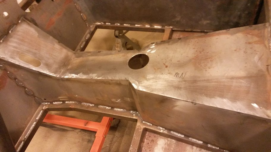
I finished most of the stitch welding and decided to have a go at the finish welding on the foot boxes and the transmission tunnel. This is not as hard as it might sound because most of the weld is ground off to leave a smooth, straight seam when the sheet metal panels are joined. The goal is to use enough weld at a high enough temperature to join the two panels, while not burning through the sheet metal or leaving too much excess weld to be ground down later. All the welding and most of the grinding for that job is now finished. Here's how the transmission tunnel looks.
I was inspired to create this website by the impending start of my next big project, building a tribute Cheetah. But before I can start on the project, I must first pick it up and bring it home. So it seemed right to begin this slightly off topic portion of the website with some words about the challenge of retrieving this kit from its current owner in Minnesota.
I have been searching the Internet for the right kit at the right price anywhere in the USA for the past five years. So, while discovering it in Minnesota was not a good as say finding it in Mississippi, it was still well within the distance I was willing to travel. But it is still a long way from Alabama to Minnesota. In addition, I have decided to take a detour on the way home to visit the man who builds the car components and will likely provide additional components and help as the project moves forward. His shop is in Ohio. All in all, I expect the trip to cover 2,800 miles and take about five days.
There was a time when a trip of that distance was mostly about finding a good audio book to help pass the time. But I admit that I'm getting older and driving for long stretches is a lot more uncomfortable now than in past years. So I decided to invite two of my best friends to come along to keep me company and share the driving duties. My nephew Bill was able to work it into his schedule and we plan to hit the road on April 22. I am most grateful for him taking time to help me with this.
With the itinerary and travel party set, I decided the time had come to replace my old pickup truck with a newer one. I could never convince myself to take a good friend on a trip in a truck with nearly 300,000 miles on it. So I got a 2014 Ford F-150 with an EcoBoost engine. So far, I like it a lot.
The one other thing I would need was a trailer to carry the Cheetah back home. After considering lots of options, I decided to build my own custom trailer starting with a stripped former boat trailer I found on craigslist. It was the right size, the right weight capacity, the right price and was a blank canvas for what I had in mind. ... Working with the car dimensions, I built a deck, complete with fenders, a winch mount and tie downs.
April 22, 2015
Bill and I hit the road around sunrise and headed north. He was great company and provided welcome relief from driving. We noted trees that had already bloomed in Alabama at earlier stages of their Spring development as we went farther north. It was like we were turning back the clock on Spring. The world didn't look profoundly different until we neared Iowa. The farms there go from horizon to horizon and are marked by perfect looking fields and picture book farm houses far back from the highway. We spend the night in Iowa City, Iowa.
April 23, 2015
We got off to an early start and arrived at Don Atkinson's home near Minneapolis, MN midday. Don was storing the car for his brother, Mark. Mark and I closed the deal and we loaded the car into the trailer. It fit like a glove. Mark and Don were very nice people and plainly car guys like us. Don showed us his Cobra replica that had been sharing space with the Cheetah. With all the parts loaded, we headed on to La Crosse, WI for the night. Bill paid me the $1 he lost when neither Mark or Don mentioned Alabama football. In his experience, people up north immediately associated people from Alabama with the UA football program. Apparently college football is not as much of a year round obsession in Minnesota.
April 24, 2015
To get to Ohio from Minneapolis, we had to drop down enough to get below the Great Lakes and go east toward Cleveland, OH. It was a full day's drive with traffic and road construction near Chicago making it harder. The worst part of that day was paying tolls every 15-20 minutes. I estimate I paid $75 in tolls in Illinois and Ohio. The coolest thing I saw was where the Interstate crossed Thornton Quarry. The bridge is 400' above the floor of the quarry and it feels like you are suspended in midair. Google it for pictures.
April 25, 2015
Bill and I visited the Cheetah shop the next morning. They showed us a nearly completed car they are assembling for a customer. Each of their cars (and each of the Cheetah's ever built) is custom in some way. No two are exactly alike. This history encourages me to build my car the way I want without being constrained by history. There were bits and pieces of the car that I liked and that I didn't like. But overall, it was a beautiful machine that sounded very intimidating when the engine started. It was very helpful to see it in person.
After an hour, Bill and I said goodbye and headed south. Our plan was to make it to Knoxville, TN for the night. On the way we realized we could make it all the way home before it got too late. The weather and traffic cleared and we pressed on. I arrive home around 10:30 PM and Bill about 45 minutes later. I had traveled more than 2,800 miles in four days and Bill topped me with about 2,900 miles. It was good to be home.
April 28, 2015
It has been my inclination from the beginning of the Cheetah project to have it powered by a traditional looking small block Chevy engine. I wanted it to resemble the 1963 Corvette engines used in the originals.
As I dug deeper into what made those engines look the way they did, I discovered that a key element was the valve covers. The iconic finned aluminum valve covers with Corvette written in script had no oil fill or breather holes in them. Later engines do have holes in the valve covers. The early engines didn't need them because the oil fill was in the intake manifold, and the breather tube was mounted in a hole in the block. More recent engine blocks do not have this hole. So to get the look I want, I will likely have an engine custom built with an intake manifold equipped with an oil fill breather and modified to accept a PCV valve.
May 2, 2015
I decided the first step on this long project was building a wooden jig to hold the fiberglass body until it is needed. The body is very light, but not thick enough to support its own weight without flexing. The jig should help it hold its shape while it sits.
The second step was mounting the suspension so the chassis can be on wheels and at something approaching ride height. That meant the 25 year old Corvette suspension pieces needed to be overhauled. In addition, I determined the differential that came with the kit was equipped with 3.07 gears. To get more lively acceleration and accommodate the double overdrive transmission I have in mind, I'll want a much lower gear ratio. The lowest I could find for this Dana 36 differential is 3.75:1. Using contacts from friends in the local dirt track racing scene, I located a shop that will overhaul the suspension and change the gears in the differential.
May 10, 2015
I've learned a lot about my project over the past few days. The originator and I have exchanged numerous emails and photos as I've figured out what I've got. It turns out that the chassis I bought was different from his current cars for three reasons. First, the design of the chassis has evolved. For example, the hinge mechanism for the doors is different and the frame piece it mounts to has changed. Second, as my car was intended as a race car by the original buyer, it was deliberately ordered without some of the pieces needed in a street car. For example, it does not have the inner fender tubs. Third, as it was intended as a race car, a few of the frame pieces are located uniquely. For example, a piece beneath the driver's foot box must be relocated to make room for the conventional pedal assembly.
May 14, 2015
Don't you just hate it when reality butts in on your dream? In this case, the dream was of a building a hot rod car without grossly overshooting the budget. Reality was in the form of a bill from the shop that rebuilt the front and rear suspension pieces for the car. The heart of the dream was a rough guess at what the job would cost based on Internet prices for various components. The sad truth was that the cost of top line parts (like I asked for) is much higher. So the bill was about double what I guessed it would be. But the good news is that the job, including rebuilding the differential with new ring and pinion gears, was done by a professional with parts that should last longer than me. And when you consider that the driver of a Cheetah is essentially surrounded by the rear differential, axles, rear wheels and suspension, it does make sense to have a professional do the job using the best parts. But I may have to wait until after I pay the next charge card bill to buy anything else for the Cheetah.
May 19, 2015
One of the things I've come to enjoy in the many projects I've undertaken is solving the myriad problems that arise. For me, a project without problems is less satisfying than one that pushed me to the limit before yielding to a clever insight or just dogged persistence. The Cheetah project is a veritable mountain of problems to be overcome, and I've spent the last week or two pondering one.
The fundamental structure of this car is a lightweight tube frame reinforced with steel sheet metal panels for added strength and rigidity. The sheet metal also forms the cockpit that separates the driver from the drive train and the outside elements. There are about ten panels that must be welded to the frame and each other like a large 3D jigsaw puzzle. What makes this puzzle particularly difficult is that it came with no instructions (e.g., which piece goes in first), and some of the pieces are not exactly the right shape to fit together. So, when piece A doesn't fit right with piece B, I'm left wondering whether to reshape A or B, and what that will do when I go to fit piece C.
Based on advice from the originator, I decided to begin with the panels for the foot boxes. These are the largest and most complexly shaped pieces. They form the outside walls of area around the driver's feet, and continue aft to form the walls of the transmission tunnel. All together, each foot box has a perimeter of almost 20', and all of it must be aligned with frame tubing and/or other panels. My efforts to install the first foot box resulted in a piece that aligned on all but about 2' of its length. Whenever I would force the misaligned piece into place, another area would jump out of place. I had resorted to cutting and grinding metal to make it fit better, but even that wasn't enough. I was about ready to cut, move and reweld a piece of the frame when another idea came to me. I realized that the entire problem could be because one factory bent corner of the foot box was slightly off. That slight error caused every part downstream from the bend to be slightly out of place, with the problem getting larger as you moved farther away from the bend. I reshaped the corner to realign the bend (no small job in itself), and everything fell into place. It would have been much faster and easier if the foot box had fit without trouble. But it was much more satisfying the way it worked out.
May 21, 2015
As I worked on the jigsaw puzzle that is the sheet metal panels for the Cheetah cabin, I decided I needed a frame rotisserie to avoid having to weld upside down. I am an occasionally barely competent welder when everything is just right, but welding upside down is just begging for molten metal to run down my arm. So I put together the rotisserie shown on the build page using two engine stands. Buoyed by that minor success, I clamped the first piece of sheet metal in place (a floor panel) and immediately saw a problem. Resting in what looked like its natural position, the panel covered a threaded hole in the frame that secures the transmission support bracket. The solution appeared to be a well placed hole drilled in the panel, but I decided to check with the originator before going farther. During our conversation, he was having difficulty visualizing the problem so i sent him a photo. That's when he realized my frame has the old transmission support bracket in the old position. I need the new bracket in the new position that does not conflict with the floor panel. .... It's a good thing I like challenges.
June 5, 2015
Work on the Cheetah for much of the past two weeks has been mental more than physical. My immediate goal was to tack weld all that needed welding so I could take the car to a professional welder for the finish work. But I discovered that I was missing several more parts. And as the list of parts to be welded grew, I made a list of all the welding jobs so I could decide the best order in which to do them. That's when the flaw in my plan became clear.
It will not be possible to tack weld everything first and then have it finish welded at one time. That is because some of the pieces obstruct access to others. So for some pieces, I will have to finish weld them before I can tack weld the next ones. If I were to have a professional do all the finish welding, I would have to transport the frame to and from him multiple times. The cost and logistics of that approach are simply not workable. So I decided to do some, but not all of the finish welding myself.
I have enough experience welding to know a good, safe weld from a "hot glue gun" type weld. So while my welds are not the prettiest I've seen, they are safe and secure. My immediate problem was that I didn't have a proper welder. But as the Car Talk guys noted, "Every project is merely an excuse to buy more tools." So I spent several days researching and then buying a MIG welder and argon gas tank. .... After days of collecting and assembling the equipment, I put two pieces of scrap steel together and set out to master the art of welding with my new welder. Ten ugly, unacceptable welds later I was beginning to question the wisdom of my decision and purchase. I had tried multiple power levels and various wire feed speeds to no avail. I was about to take a break to lower my frustration level when I thought about changing the rate at which the argon gas flows around the arc to protect the weld. That's when I discovered that I had forgotten to turn on the gas. $**^&#%( .... With the shielding gas flowing, the welder starting making very acceptable, even decent looking welds.
So, my plan for now is to do the tack welding and hard to access finish welding myself. I figure that by the time I get to the "in plain sight" finish welding, I'll either be content with the quality of my own welds, or I'll take it to a professional for the final work. Either way works for me.
July 13, 2015
Summer vacations and life in general have taken time from my build. But I have finished nearly all of the tack welding and begun some of the stitch welding. There are a few places where the welds need to be very good, but most of them won't show in the finished car. So I decided to have a go at the stitch welding. I started by rolling the frame over on the rotisserie so I could practice on joints that won't be seen. I learned that I can do a decent job welding downhill and from right to left, so I'll do all that I can using that approach.
July 30, 2015
I finished most of the stitch welding and decided to have a go at the finish welding on the foot boxes and the transmission tunnel. This is not as hard as it might sound because most of the weld is ground off to leave a smooth, straight seam when the sheet metal panels are joined. The goal is to use enough weld at a high enough temperature to join the two panels, while not burning through the sheet metal or leaving too much excess weld to be ground down later. All the welding and most of the grinding for that job is now finished. Here's how the transmission tunnel looks.
August 22, 2015
With most of the welding and grinding finished, I decided to remove the surface rust and protect the steel with a coat of primer. I decided a media blaster was the right tool for the job and found my old siphon style sand blaster last used in 2002. Two things have changed since then, not counting my age. One is that the Internet is now filled with information about blasting, and the other is that no one now uses sand because of the dire health hazard associated with silicon dust. So I bought some safer media (aluminum oxide) and gave it a try. My siphon blaster would not pick it up. It is apparently denser than sand and harder for the air stream to vacuum up. So off I went to Harbor Freight to buy a small cannister style blaster. .... Did I mention how happy I am that Harbor Freight opened a store nearby in Opelika?
Learning to use the new blaster has been a slow, start and stop, trial and error process. There are multiple ways a blaster can stop working and it took time to experience them all and discover the quickest ways to identify and clear the problems. In addition, the summer time humidity has been right at 100% making it easy to get water into the cannister to gum up the media. That and the need to wear full body protection in August has made blasting something I don't want to do again. But I'm about 25% finished and getting a little quicker each time I suit up. I hope to have the blasting finished and a coat of primer on the frame by Labor Day.
August 26, 2015
A few days ago a friend told me about a man who recently expanded his welding business to include powder coating for large projects. I spoke with him about powder coating my chassis some time next year. He quoted me a good price and showed me the very large oven he has to bake on the powder. He also told me he would prep the chassis and discouraged me from painting it with primer. Fortunately I had not done much, so my job just got a lot easier. I finished blasting the most obvious rust spots and moved on to assembling the suspension.
The front suspension is based on the A-arms of a 1990 Corvette that have been modified to accept an adjustable coil-over spring and shock assembly by QA1. The manual steering rack is a custom piece made to the originator's specifications by Flaming River. At this point I am just bolting the suspension together with eyeballed alignment so I can roll the chassis around for the next part of the project.
September 12, 2015
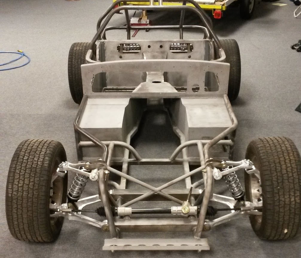
I expected the task of assembling the front and rear suspensions to take a day or so. I was wrong. It turns out the front suspension control arms I acquired with the car were from the wrong vintage Corvette. As they had no identifiable markings on them, I only discovered that after they were cleaned, mounted with new ball joints and installed on the chassis. They were too short for the steering system. With the problem identified, I obtained control arms from the correct vintage Corvette and took on the task of cleaning them and mounting new bushings and ball joints. That took about ten days. With temporary wheels and tires mounted, the front suspension now looks like this.
A few days ago a friend told me about a man who recently expanded his welding business to include powder coating for large projects. I spoke with him about powder coating my chassis some time next year. He quoted me a good price and showed me the very large oven he has to bake on the powder. He also told me he would prep the chassis and discouraged me from painting it with primer. Fortunately I had not done much, so my job just got a lot easier. I finished blasting the most obvious rust spots and moved on to assembling the suspension.
The front suspension is based on the A-arms of a 1990 Corvette that have been modified to accept an adjustable coil-over spring and shock assembly by QA1. The manual steering rack is a custom piece made to the originator's specifications by Flaming River. At this point I am just bolting the suspension together with eyeballed alignment so I can roll the chassis around for the next part of the project.
September 12, 2015
I expected the task of assembling the front and rear suspensions to take a day or so. I was wrong. It turns out the front suspension control arms I acquired with the car were from the wrong vintage Corvette. As they had no identifiable markings on them, I only discovered that after they were cleaned, mounted with new ball joints and installed on the chassis. They were too short for the steering system. With the problem identified, I obtained control arms from the correct vintage Corvette and took on the task of cleaning them and mounting new bushings and ball joints. That took about ten days. With temporary wheels and tires mounted, the front suspension now looks like this.
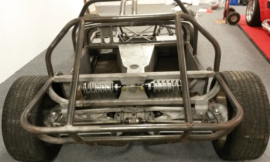
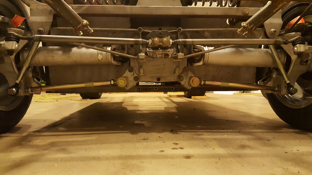
With the front suspension done, I started assembling the rear. As it is an independently sprung rear suspension sourced from a C4 Corvette, each wheel hub is positioned by five components starting with the half-shafts that connect the hub and spindle to the differential. Two trailing arms position the hub fore and aft, and control the caster angle. The lower control arm controls the camber angle and the aft control arm controls the toe in/out angle. The unique design of this car replaces the stock monospring that sits beneath the assembly on a Corvette with two coil-over shock absorbers mounted horizontally above the assembly. To connect the hub to the coil-overs, there are push rods from the lower hub to a bell-crank that translates the vertical movement of the wheels to horizontal movement of the coil-overs. All of that means that the five independent pieces must be fit, connected and properly adjusted for the system to function. Here's what it looks like when assembled.
It took about two days for me to assemble the rear suspension working only from a few photos and a general understanding of Corvette suspensions. The first challenge was that the suspension sits very close to the frame, leaving little room to maneuver while installing bolts, nuts, etc. The second challenge was that adjusting any one control arm affected the adjustment of the others. So adjusting one arm to gain a little space in one place would reduce the clearance elsewhere. The third challenge was that the push rod that connects the bottom of the hub to the coil-over fits in a very narrow space that has three potential places to rub. After several failed attempts, my last approach was to position the coil-over and push rod first and then connect the control arms one at a time while assuring the push rod did not rub on anything. It did not work. One last trailing arm would not fit. It was too long. :-(
I contacted the originator about the problem. He asked about the length of the trailing arms and then noted that he was now using arms about a inch shorter. I made a temporary change to the troublesome trailing arm to shorten it by a half inch and everything fell into place.
My next task is to pack up the car for a trip to Ohio so the originator can guide me through the job of mounting the body on the chassis.
September 28, 2015
I spent Monday through Friday of last week at the originator's shop in Ohio. Every day I was glad I took the car to him rather than trying to do the job by myself. Much of the work required two or three people and some of it would have taken me weeks and multiple false starts to finally get right. Here are the highlights of what was done:
We all worked hard all day for five days but it was well worth it. There is still much to do, but I've made a big step forward.
October 8, 2015
When I got the car home from Ohio, the body and nose were firmly attached to the frame. So the first thing I did was build two fixtures so I could remove the body and nose to have better access to the frame. That allowed me to finish some of the tack welding done in the Ohio shop.
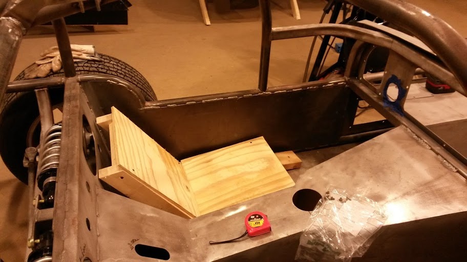
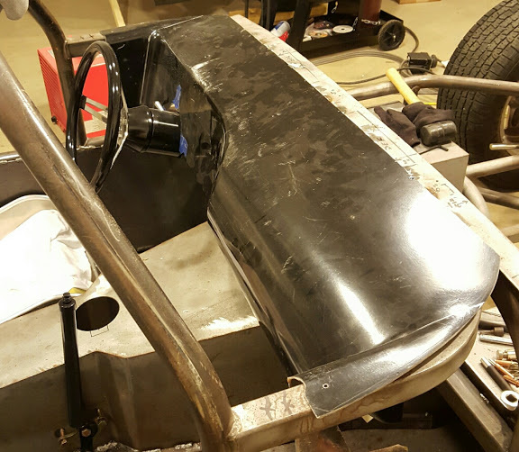
My next step was to test out the seating position for the driver. That is a critical decision because if affects many other things. I started by building a wooden mockup of a seat with a 25 degree layback. I used the thickness of the wooden frame to approximate a seat slide system and cushions, and put it where it seemed to fit. A test sit caused me to raise the front of the seat so my legs could have a bend at the knees. With the driver's position feeling comfortable, I tried out the imaginary shifter and held the steering wheel where it felt natural. That allowed me to temporarily position the steering column and envision the linkage that will connect it to the steering rack. Finally, I slid the floor mounted pedal assembly into the foot box to see where it best fit me. I determined there was plenty of room for it. Here's a picture of the mockup seat.
I contacted the originator about the problem. He asked about the length of the trailing arms and then noted that he was now using arms about a inch shorter. I made a temporary change to the troublesome trailing arm to shorten it by a half inch and everything fell into place.
My next task is to pack up the car for a trip to Ohio so the originator can guide me through the job of mounting the body on the chassis.
September 28, 2015
I spent Monday through Friday of last week at the originator's shop in Ohio. Every day I was glad I took the car to him rather than trying to do the job by myself. Much of the work required two or three people and some of it would have taken me weeks and multiple false starts to finally get right. Here are the highlights of what was done:
- The fiberglass body (from the firewall to the tail) was temporarily attached to the tube frame while the rear wheel tubs were temporarily put in place and marked for bonding to the body.
- The wheel tubs were then bonded to the body with epoxy glue.
- The fiberglass stringers (vertical supports that run from the front to the back of the hood) were positioned and bonded to the front half of the car with epoxy glue.
- The body was removed from the tube frame and the glued joints were reinforced with fiberglass. Similarly, the stringers were fiberglassed to the hood.
- Some additional small fiberglass filler panels were glued and then fiberglassed into place.
- Two pieces of the tube frame were cut out to make room for a new overhead tube for the new hinge system for the doors. The new tube was fabricated and tack welded into place.
- The body was placed back on the tube frame and secured with temporary fasteners.
- Body support brackets were custom shaped to fit the body,tack welded to the frame and attached to the body.
- Front and rear windshield openings were trimmed for size and both windows were installed to stiffened the body structure.
- The front half of the car was put in place and the hinge system that allows it to pivot up from the front was installed.
- The doors and hinge system were fitted and assembled. This was a very time consuming and tedious process that involved trimming the door openings and the inner and outer door panels. The hinges also had to be attached to the doors and support brackets that were custom fit and welded to the frame. Finally the inner and outer doors had to be glued together while aligned with each other and the door openings.
We all worked hard all day for five days but it was well worth it. There is still much to do, but I've made a big step forward.
October 8, 2015
When I got the car home from Ohio, the body and nose were firmly attached to the frame. So the first thing I did was build two fixtures so I could remove the body and nose to have better access to the frame. That allowed me to finish some of the tack welding done in the Ohio shop.
My next step was to test out the seating position for the driver. That is a critical decision because if affects many other things. I started by building a wooden mockup of a seat with a 25 degree layback. I used the thickness of the wooden frame to approximate a seat slide system and cushions, and put it where it seemed to fit. A test sit caused me to raise the front of the seat so my legs could have a bend at the knees. With the driver's position feeling comfortable, I tried out the imaginary shifter and held the steering wheel where it felt natural. That allowed me to temporarily position the steering column and envision the linkage that will connect it to the steering rack. Finally, I slid the floor mounted pedal assembly into the foot box to see where it best fit me. I determined there was plenty of room for it. Here's a picture of the mockup seat.
Working from the mockup seat measurements, I began researching the best seat options. My priorities were, in order, comfort, appearance, adjustability and ease of installation. Because the opening for the seat is small, I found myself looking at bomber style seats made of various materials. I settled on a Kirkey Vintage aluminum racing seat and mount. The mount allows the seat position to be adjusted some, but is entirely manual with nuts and bolts. I took some careful measurements and then ordered one seat to try out.
By the way, its a good thing I'm not a really big guy. About the only way that could be done would be to wrap my backside in wax paper and then plop it down in some freshly made expanding foam until it hardened. The foam could then be used as a mold to fabricate a custom seat. I bet it would be comfortable when done, but it would only fit one person's butt.
October 17, 2015
The Kirkey seat arrived and fits like a glove. I'll have to weld in some supports to get the height where I want it, but otherwise it fits fine. I mocked up some seat cushions from foam left over from other projects and it was very comfortable.
I realized there was more finish welding to do and spent a day or so welding and grinding. The weather has been so nice that I rolled the car outside for some of the work. I love Autumn weather.
Returning to work on the cockpit, I began thinking about how to mount the pedal assembly to the floor. The original design has slots in the steel floor for the mounting bolts. That allows the pedal assembly to be move fore and aft to fit the driver. It's finished it off with a large steel plate beneath the floor that acts like a giant washer for the bolts. It reinforces the floor and seals the slots against the weather. I may do that, or I've been thinking of an alternative approach. I'll describe it later if I go that way.
Thinking about the pedals started me thinking about the rest of the brake system. Between the pedals on one end and the calipers on the other end is a very large number of rods, master cylinders, hoses, hard lines and multiple fittings. The tricky part is getting the various plumbing pieces to come together so it is both functional (i.e., leak free, easy to service, well secured, and away from hot stuff) and attractive (i.e., neat, clean, rust free and inconspicuous). I spent most of a day researching and locating the various components. This is one of those jobs where you need to know where you can get every single piece in advance, because if one piece is not available, it can make everything else worthless. My shopping list for the brake system is about 40 parts.
Another task that requires a great deal of thought and consideration is the selection of tires and wheels. I started with the rear tires. I want tires that provide good traction and also fill up the wheel wells like they did back in the 1960s. The challenge is that the highest performing modern tires have a very low profile (rubber band tires) that doesn't look right on a Cheetah. The best option came to me while watch Stacey David build his Cheetah on his TV show, Gearz. I decided to use the same type of tire he used, Mickey Thompson Sportsman SR. These tires have a reputation for good traction, are DOT legal, and can be obtained in "old school" sizes.
Starting with the temporary wheels and tires now mounted on the Cheetah, I took measurements to determine how much room I have for tires. I built a spreadsheet that allowed me to input the dimensions of various tires and compare them to the space available. I determined that I should be able to fit a 28x10-18 tire on the rear. That means I will need an 18" wheel that is 8.5" to 10" wide and has the correct backspace to locate the tire. (Backspace describes the distance between the mounting surface of the wheel and the inside face of the wheel. The correct backspace keeps the tire from rubbing either the frame on the inside or the fender on the outside.)
Selecting wheels is more about appearance and cost after the size is determined. I looked at lots of pictures and settled on a modern version of the traditional five spoke magnesium wheel that would have been common on Cheetahs in 1965. Of course the modern ones are not magnesium and look a little different because of the larger size, but I'm happy with the one I selected. It is called a Vision 142.
Because fitting wheels and tires on a real car is not the same as doing it on a spreadsheet, I've decided to order just two at first. That will allow me to check out the actual fit on both rears, and I can try them both on one side to better see what size fronts I want to use.
October 26, 2015
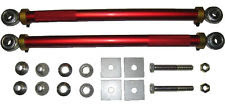
There are two welding jobs that are so close to the rear suspension that I will have to remove it. I also need to replace the incorrect heim joint control arms I installed temporarily when I took the car to Ohio. So I decided to remove the rear suspension. While thinking about that I was also thinking about the originator's suggestion to replace the factory control arms that adjust and control toe in and camber. He suggested aftermarket replacements that use heim joints for easier adjustment. They are available from several vendors, but they are not inexpensive.
As I looked at photos of the replacement parts, it seemed to me they were little more than threaded tubes with rod ends. So I decided to see if I could assemble the parts to build my own. Here is a picture of the camber control rod.
It didn't take long to locate the tubes and rod ends, but two challenges remained. First, the system for the toe rods requires a bracket that bolts to the differential and secures the inside ends of the control rods. I decided to build my own bracket by welding one from plate steel. Second, the outer ends of the toe rods must attach to the hub using tapered tie rod ends. No problem, thought I, I'll just use stock tie rod ends that will screw into the threaded tube. WRONG! I won't make you good readers suffer through the three days of Internet searching that I did trying to solve the problem, but I will note the important things I learned.
By the way, its a good thing I'm not a really big guy. About the only way that could be done would be to wrap my backside in wax paper and then plop it down in some freshly made expanding foam until it hardened. The foam could then be used as a mold to fabricate a custom seat. I bet it would be comfortable when done, but it would only fit one person's butt.
October 17, 2015
The Kirkey seat arrived and fits like a glove. I'll have to weld in some supports to get the height where I want it, but otherwise it fits fine. I mocked up some seat cushions from foam left over from other projects and it was very comfortable.
I realized there was more finish welding to do and spent a day or so welding and grinding. The weather has been so nice that I rolled the car outside for some of the work. I love Autumn weather.
Returning to work on the cockpit, I began thinking about how to mount the pedal assembly to the floor. The original design has slots in the steel floor for the mounting bolts. That allows the pedal assembly to be move fore and aft to fit the driver. It's finished it off with a large steel plate beneath the floor that acts like a giant washer for the bolts. It reinforces the floor and seals the slots against the weather. I may do that, or I've been thinking of an alternative approach. I'll describe it later if I go that way.
Thinking about the pedals started me thinking about the rest of the brake system. Between the pedals on one end and the calipers on the other end is a very large number of rods, master cylinders, hoses, hard lines and multiple fittings. The tricky part is getting the various plumbing pieces to come together so it is both functional (i.e., leak free, easy to service, well secured, and away from hot stuff) and attractive (i.e., neat, clean, rust free and inconspicuous). I spent most of a day researching and locating the various components. This is one of those jobs where you need to know where you can get every single piece in advance, because if one piece is not available, it can make everything else worthless. My shopping list for the brake system is about 40 parts.
Another task that requires a great deal of thought and consideration is the selection of tires and wheels. I started with the rear tires. I want tires that provide good traction and also fill up the wheel wells like they did back in the 1960s. The challenge is that the highest performing modern tires have a very low profile (rubber band tires) that doesn't look right on a Cheetah. The best option came to me while watch Stacey David build his Cheetah on his TV show, Gearz. I decided to use the same type of tire he used, Mickey Thompson Sportsman SR. These tires have a reputation for good traction, are DOT legal, and can be obtained in "old school" sizes.
Starting with the temporary wheels and tires now mounted on the Cheetah, I took measurements to determine how much room I have for tires. I built a spreadsheet that allowed me to input the dimensions of various tires and compare them to the space available. I determined that I should be able to fit a 28x10-18 tire on the rear. That means I will need an 18" wheel that is 8.5" to 10" wide and has the correct backspace to locate the tire. (Backspace describes the distance between the mounting surface of the wheel and the inside face of the wheel. The correct backspace keeps the tire from rubbing either the frame on the inside or the fender on the outside.)
Selecting wheels is more about appearance and cost after the size is determined. I looked at lots of pictures and settled on a modern version of the traditional five spoke magnesium wheel that would have been common on Cheetahs in 1965. Of course the modern ones are not magnesium and look a little different because of the larger size, but I'm happy with the one I selected. It is called a Vision 142.
Because fitting wheels and tires on a real car is not the same as doing it on a spreadsheet, I've decided to order just two at first. That will allow me to check out the actual fit on both rears, and I can try them both on one side to better see what size fronts I want to use.
October 26, 2015
There are two welding jobs that are so close to the rear suspension that I will have to remove it. I also need to replace the incorrect heim joint control arms I installed temporarily when I took the car to Ohio. So I decided to remove the rear suspension. While thinking about that I was also thinking about the originator's suggestion to replace the factory control arms that adjust and control toe in and camber. He suggested aftermarket replacements that use heim joints for easier adjustment. They are available from several vendors, but they are not inexpensive.
As I looked at photos of the replacement parts, it seemed to me they were little more than threaded tubes with rod ends. So I decided to see if I could assemble the parts to build my own. Here is a picture of the camber control rod.
It didn't take long to locate the tubes and rod ends, but two challenges remained. First, the system for the toe rods requires a bracket that bolts to the differential and secures the inside ends of the control rods. I decided to build my own bracket by welding one from plate steel. Second, the outer ends of the toe rods must attach to the hub using tapered tie rod ends. No problem, thought I, I'll just use stock tie rod ends that will screw into the threaded tube. WRONG! I won't make you good readers suffer through the three days of Internet searching that I did trying to solve the problem, but I will note the important things I learned.
- The rear tie rod ends Corvette used on its C4 were one of the few manufactured with male mounting threads. They were discontinued and are now considered rare and expensive to buy.
- The threads on the C4 rear tie rod ends are an uncommon metric size. No one in the USA, Europe or Australia manufactures a ready-to-use threaded tube in that size.
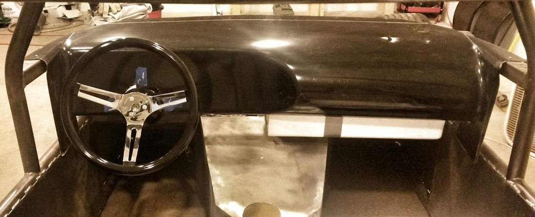
The past few days were spent sorting out the dash and the steering column. The dash is a molded fiberglass piece that must be cut and fitted for the car. It can be moved fore and aft, and the steering column can be moved up and down, so I have to figure out both at the same time to know where to cut the hole in the dash for the column.
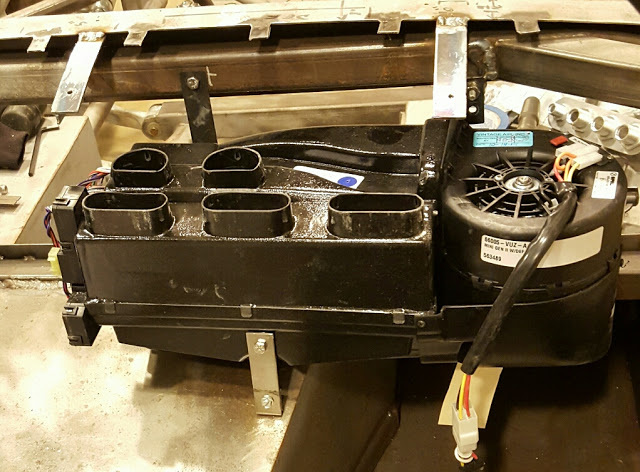
I've decided the car will be too hot to drive during much of the summer without air conditioning. So I researched and found a very compact HVAC unit to fit inside the car. Using data from the manufacturer I built a mockup of the HVAC to be sure it will fit behind the dash when it is in place. With the mockup in place, I used trial and error to find the best position for the steering wheel (and column) and, subsequently, the dash. It turns out I will have to modify the dash near the passenger to better hide the HVAC. I'll also add a piece between the transmission tunnel and the dash to hold the control panel for the HVAC. Lastly, I'll have to modify the flanges on each side of the dash to better fit with and cover the frame that supports the dash.
One of the more interesting (i.e., troubling) problems I encountered while sorting out the dash was making room for the driver to enter the car. At each step of the trial-and-error process, I would place the seat in the car and climb in to test the location of the steering wheel. I found that even with the steering column mounted as high as possible and well forward, there was very little room for my legs when getting into the seat. Keep in mind that I am only 5'6" tall and the body is not on the frame at this point. Using the upper frame like a jungle gym I could maneuver my feet into place and slide down into the seat while supporting my body with my hands. It was snug like the cockpit of some of my old jets once I got in, but getting in and out was not easy. .... All of the solutions that gave me more room to get in resulted in less comfortable seating. I was getting concerned until I remembered that the steering column tilts. I have not yet installed the levers that tilt the column, but I will do that soon and see if the extra room afforded by the tilted column solves the problem. It that does not solve the problem, I may have to use a removable steering wheel like the one installed in my Cobra. Here are some pictures of the dash and steering column in their final positions. The white box under the dash is the mockup of the HVAC unit.
October 29, 2015
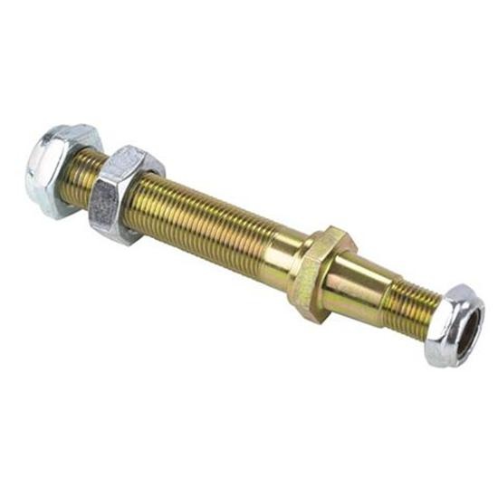
Bad news. The Adjustable Tie-Rod Adapter arrived and is not the right size. The tapered part of the rod is smaller than the hole it goes into. I renewed my search both online and at local parts stores today. The turning point was when my NAPA parts man showed me a book describing about 300 tie rod ends including the key dimensions of each one. I took three things from seeing that book. First, there are way too many different sizes of tie rod ends to get lucky picking one. Second, you need to use a computer to make the search for the right size part feasible. And third, there likely is a tie rod end that could be used for my purpose. When I got home I resumed the search on the Internet. I ultimately found a rod end intended for another car that will likely work for my project. I found one for sale on Ebay for less than $10 including shipping so I bought it just to see if it will work. It looks like it will be next week before I know if the search for this particular part is over.
November 7, 2015
The cheap Ebay tie rod end is too big. The search goes on.
November 16, 2015
Physical progress on the Cheetah has stopped and will remain dormant for several more weeks as I recover from surgery to repair a torn rotator cuff in my right (dominant) arm. But I have been using this down time to sort out and source some of the parts I will need later. For example, I have homed in on a preferred door latch system, headlights and buckets, and custom headers and exhaust system. I've also been working through the best sequence in which to do the many jobs that remain. I hope the time I spend now, while I can't do anything else anyway, will save me time later on.
December 2, 2015
My shoulder is getting better, but is nowhere near strong enough to work on the car. However, with my shopping list filled out, I took advantage of the Black Friday / Cyber Monday sales to order some of the things that were discounted. I'll be seeing a lot of the UPS man in the coming days. It's always fun to look at new parts.
The search for a new tie rod end for the rear suspension has come to an end. I'll be using the stock tie rod end in a rod I will fabricate. It will work as well as what I wanted but will cost a little more and be more work.
January 1, 2016
It's been about two months since my surgery and I'm starting to resume work on the car. I have to be careful not to demand too much of my right shoulder, but I feel fine for some of the smaller jobs. Over the past few days I have been fabricating the components for the new rear toe control rods. I built a new bracket out of plate steel to secure the new rod ends to the differential case. I also welded the seat belt mounting plates in place. My welding wouldn't impress Jesse James, but it's plenty strong enough.
January 7, 2016
When I was preparing the car for the trip to Ohio last fall, I discovered that some of the rear suspension pieces were the wrong size. I made it work well enough for the trip, but I knew the rear suspension would have to come off again to fit the correct pieces. I also needed to weld the seat belt mounting brackets and the differential support bracket without damaging the nearby suspension pieces. So I pulled the rear suspension and did the needed welding. I'm now about half done reassembling the rear suspension with the new camber and toe rod assemblies I have fabricated. Manhandling those cumbersome suspension pieces into place was a good opportunity to test out my repaired shoulder. I tried not to demand too much of it and so far it feels fine.
January 17,2016
My shoulder is getting stronger every day, so I won't be saying more about it unless a problem arises.
I finished assembling the rear suspension with the new control rod assemblies I made for the camber and toe adjustments. Two modifications to the stock Corvette rear suspension designed for this car make it very challenging to get everything to fit right. First, the remote coilover shocks require rods from the bottom of each hub to the bellcrank for each shock. Each rod fits in a very narrow gap between the halfshaft and the hub assembly. This small space limits the adjustment that can be made to the trailing arms to move the hub fore and aft. Second, the frame where the trailing arms connect is only slightly narrower than that required by the width of the suspension assembly. This causes any significant toe-in adjustment to cause the trailing arms to rub on the frame. It was possible to get everything to fit, but it was a tedious process. I suspect the clearances will improve when the weight of the drivetrain is added and suspension is in its compressed position.
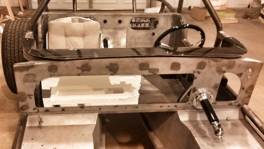
My next job required a helper as it involved putting the fiberglass body on and off the car several times. My grand-niece Lina was my gracious and beautiful helper. Fortunately, the body is very light so the two of us moved it without difficulty. .... The body and the fiberglass dash panel both rest on the metal frame near the firewall. It was necessary to trim the dash piece to fit snuggly with the body without pushing it out of position. It was the kind of job where you cut a little at a time to avoid cutting too much and creating a much bigger problem. By the fourth time, we were getting good at moving the body and the job was finished.
January 20, 2016
The original design of the dash panel allowed it to rest on the frame at the front and on both sides. But the originator noted that installing the dash that way would mean it could not be removed without first removing the entire fiberglass body. He suggested cutting off the side pieces so the dash could come out cleanly if needed. Unfortunately, the side pieces were originally intended both to support the dash and to establish its position and orientation. If I removed them before installing new support brackets for the dash, the dash might be misaligned.
Work on the dash panel continued as I designed and fabricated some metal brackets that will be welded to the frame and support the dash. This time the trial and error process involved slowly bending lengths of flat steel to follow the curve of the dash panel. Once the curved pieces are right, I'll weld them and support pieces into place as brackets for the dash.
February 9, 2016
Cold weather has slowed my pace a bit, but I did finish the dash support brackets. I then fabricated brackets to support the HVAC evaporator that must fit behind the dash. The final position looks like this.
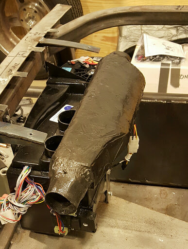
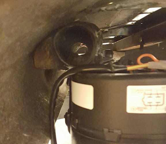
The HVAC unit has two smaller defrost outlets and three larger air outlets. The kit provided duct hose to fit each of the outlets. Not surprisingly, there is not enough room between the dash and the HVAC to fit and route all three air ducts. I decided the solution was to fabricate a custom air manifold out of fiberglass to fit over the three air ducts and redirect the air to two outlets - one for the driver and one for the passenger. I did a little research and decided to try the "lost foam" method of fabrication.
The first step was to sculpt a piece of styrofoam into the shape of the inside of the manifold. I thought of it as making a model of the air that would be inside the manifold. The key points were to make it fit the existing HVAC outlets, fit within the available space behind the dash, and provide outlets for ducts to the driver and passenger. After some trial and error fitting, I declared the styrofoam model complete and covered it with tape to protect it from the fiberglass resin that would follow. In retrospect I wish I had protected the foam with a coat of watered down wood glue instead. It would have followed the contours of the model better and would have been less of a problem later in the process.
With the model protected, I wrapped it in fiberglass and resin and let it set. When it was hard, I added a second layer for strength. When the second layer was hard, I pour acetone into the open ends of the piece and watched it melt the styrofoam. (This is the lost foam step.) When most of the foam was gone I scraped out the rest and the bothersome tape through the various openings.
I thought I was nearly through until it came time to test fit the piece. That's when I discovered that it needed a lot more shaping and filling to fit in the very tight space it was made for. I ground away, reshaped and recovered the new holes I created about a dozen times before it was both air tight and snug enough to fit. Here's what the final piece looks like.
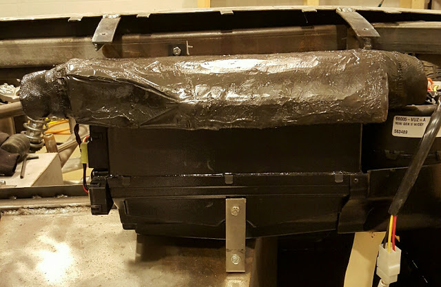
And here is proof that it actually fits behind the dash. One photo of it under the dash and another from the outside.
Yes, I know my first fiberglass fabrication job is not up to the standards of the Ridler or Konigsegg, but part of the fun of this project for me is doing something I haven't done before. Besides, it will never be seen by anyone but me and the millions of people who visit this web site. So I'm ok with it.
May 9, 2016
It's been a while since I've worked on the Cheetah. With Spring approaching, I began getting my pontoon boat ready for the coming Summer on the lake. I won't go into the details here, but it took a while to get everything sorted out. The payoff came yesterday when I spent most of the day on Lake Martin with my family. The boat worked flawlessly and I slept better last night than I have in years. Life is good.
I had been searching for an affordable Cheetah project for years before I came across the one I now have. When it popped up I was in the middle of a project to upgrade the interior of my 1963 Corvette. That project went on hold while I played with my new toy. I recently realized that its been about two years since the Corvette last ran under its own power. Concerned that it could develop problems just from lack of use, I decided to finish it before I resume work on the Cheetah. So it will be some time before work on the Cheetah continues.
On a different topic, I recently encountered a particularly unpleasant person on the Internet. He is no more offensive to me than to anyone else. He is just a sad, unhappy man of below average intelligence. My encounter with him reminded me of those moments we have all seen when some jerk at the store or in his car does something stupid and then yells at us as if we had done something wrong. My reaction for a long time has been to feel a sense of gratitude. I'm grateful that I am not that person. Because while I had to put up with him for a few moments, he has to live with himself every second for the rest of his life. It must be awful for him to wake each morning and realize he is still himself.
August 9, 2016
Three months after my last post I am nearing the end of my effort to upgrade the interior of my Corvette. I'll post pictures when it is finished, but here is a list of the major work.
My goal in the above work was to make the car safer and more comfortable while minimizing any permanent changes to the stock elements of the car. Other than a few new holes in the fiberglass and two nuts welded to the frame (for the shoulder harnesses), none of the original components were affected. And all the old stuff has been stored away in case it is ever needed.
Of course I also discovered and fixed a number of maintenance items unrelated to upgrading the interior. It's been fifteen years since I last did major work on the car, so its not surprising that some things needed attention.
August 24, 2016
The last major hurdle in my effort to revitalize my Corvette was cleared last night. Thanks to the help, guidance and expertise of my nephew and good friend, Robert Capps, the windshield is back in place. Robert came over after a long day at his job to lend a hand. It was a messy job due to the sticky bedding compound I used to stop leaks, but we got it seated in less than an hour. It will likely take longer than that to clean up all the compound we spread around, but that is just work. Putting the windshield was more like solving a three dimension puzzle covered in syrup while wearing gloves.
September 7, 2016
The most visible parts of the Corvette project are now complete. Here's what the new interior looks like.
May 9, 2016
It's been a while since I've worked on the Cheetah. With Spring approaching, I began getting my pontoon boat ready for the coming Summer on the lake. I won't go into the details here, but it took a while to get everything sorted out. The payoff came yesterday when I spent most of the day on Lake Martin with my family. The boat worked flawlessly and I slept better last night than I have in years. Life is good.
I had been searching for an affordable Cheetah project for years before I came across the one I now have. When it popped up I was in the middle of a project to upgrade the interior of my 1963 Corvette. That project went on hold while I played with my new toy. I recently realized that its been about two years since the Corvette last ran under its own power. Concerned that it could develop problems just from lack of use, I decided to finish it before I resume work on the Cheetah. So it will be some time before work on the Cheetah continues.
On a different topic, I recently encountered a particularly unpleasant person on the Internet. He is no more offensive to me than to anyone else. He is just a sad, unhappy man of below average intelligence. My encounter with him reminded me of those moments we have all seen when some jerk at the store or in his car does something stupid and then yells at us as if we had done something wrong. My reaction for a long time has been to feel a sense of gratitude. I'm grateful that I am not that person. Because while I had to put up with him for a few moments, he has to live with himself every second for the rest of his life. It must be awful for him to wake each morning and realize he is still himself.
August 9, 2016
Three months after my last post I am nearing the end of my effort to upgrade the interior of my Corvette. I'll post pictures when it is finished, but here is a list of the major work.
- Replaced the stock manual steering with a power steering system
- Replaced the stock steering column with an aftermarket tilt steering column and new smaller steering wheel
- Replaced stock electrical plugs at firewall with custom units
- Removed and stored the stock instrument panel and center console equipment
- Fabricated and installed a new instrument panel and center console using custom designed gauges
- Replaced radio with hidden BlueTooth based sound system
- Replaced the entire aftermarket air conditioning system with a new system custom fit to my car
- Customized under-dash wiring to accomodate new electrical equipment
- Replaced the stock low-back bucket seats with rebuilt seats from a C4 Corvette
- Replace the stock lap belts with three-point seat belt / shoulder harnesses
- Fabricate and install a custom center armrest/console with cup holder
- Remove leaky windshield and reinstall with new rubber seal
My goal in the above work was to make the car safer and more comfortable while minimizing any permanent changes to the stock elements of the car. Other than a few new holes in the fiberglass and two nuts welded to the frame (for the shoulder harnesses), none of the original components were affected. And all the old stuff has been stored away in case it is ever needed.
Of course I also discovered and fixed a number of maintenance items unrelated to upgrading the interior. It's been fifteen years since I last did major work on the car, so its not surprising that some things needed attention.
August 24, 2016
The last major hurdle in my effort to revitalize my Corvette was cleared last night. Thanks to the help, guidance and expertise of my nephew and good friend, Robert Capps, the windshield is back in place. Robert came over after a long day at his job to lend a hand. It was a messy job due to the sticky bedding compound I used to stop leaks, but we got it seated in less than an hour. It will likely take longer than that to clean up all the compound we spread around, but that is just work. Putting the windshield was more like solving a three dimension puzzle covered in syrup while wearing gloves.
September 7, 2016
The most visible parts of the Corvette project are now complete. Here's what the new interior looks like.
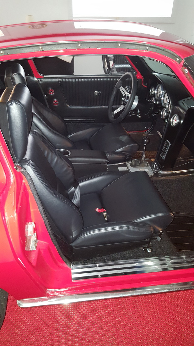
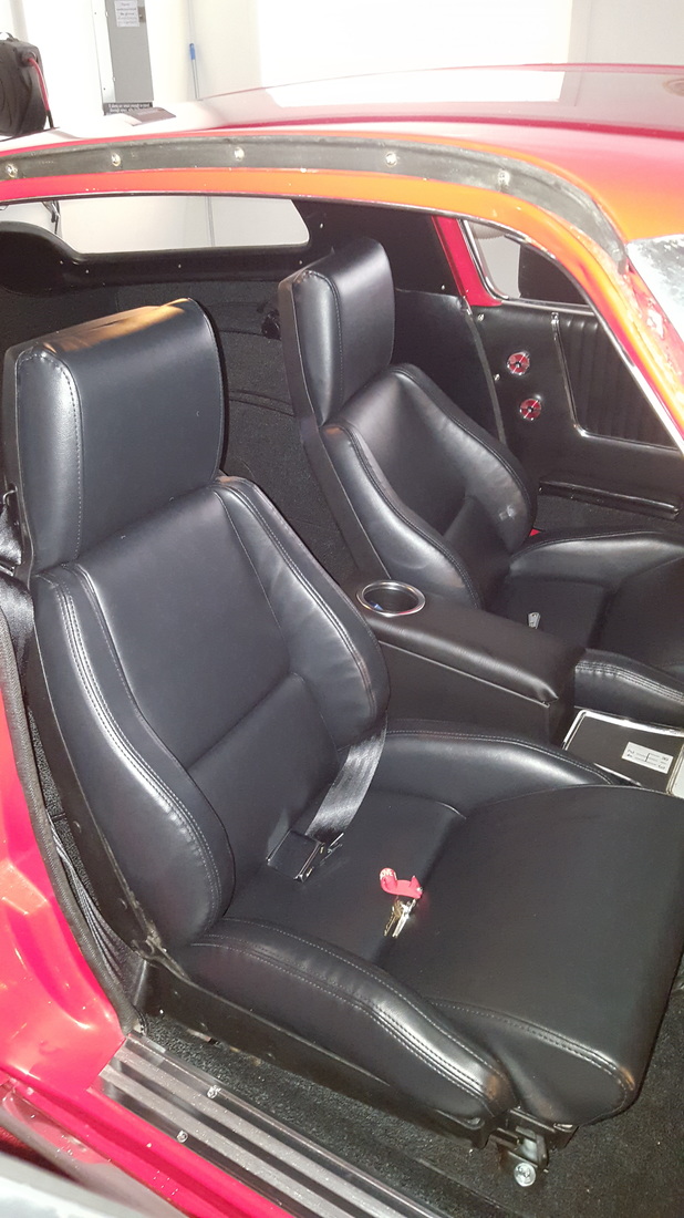
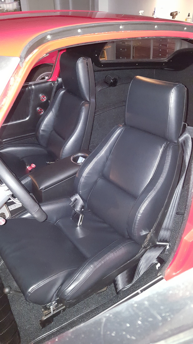
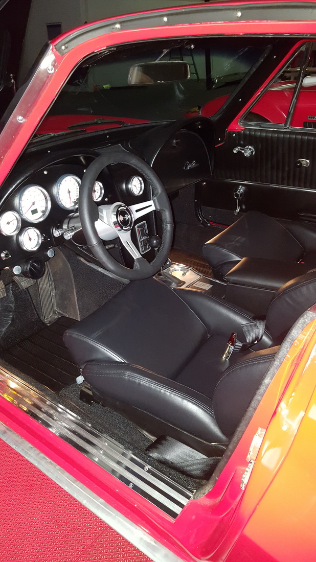
The first drive revealed a few minor problems and one significant new one. The brakes were spongy and inspection revealed a leaking front caliper. As soon as that is fixed, it should be ready for routine use.
September 18, 2016
Work on the Corvette is about as complete as work on a 53 year old car can get. In other words, there is always something that needs attention. But its driveable, safe and comfortable, so I'll just make a list of things for future work.
You'd think that would free me up to work on the Cheetah, but I've taken on a different task for now. I'm doing some long overdue work on my building and property now that the temperature is starting to moderate a little. I hope to be finished with that and back at work on the Cheetah by October.
November 15, 2016
Work on the Cheetah resumed in earnest a week ago. The next big step is installing the drivetrain to see how everything fits with the weight of the engine and transmission in place. To do that I had to finalize my decisions on the engine, transmission and driveshaft. Here's what I'm going to use.
This car was designed and constructed to use these components so they should all fit. But the engine mounts have to be custom fit to allow the proper alignment of the drivetrain. That means I will need to place the entire drivetrain in position using an engine hoist and then weld the engine mount brackets to the frame. I've obtained the driveshaft and ordered the transmission/clutch/bell housing assembly. But as I don't want a freshly built engine sitting for months (or years) before I finish the car, I've decided to use an old Chevy engine to mock up the drivetrain and fit the engine mounts. Fortunately, my nephew Bill Capps has two old race engines in storage in my building. I'll use one of them for now.
The original Cheetah had the engine placed so far rearward that it had no driveshaft. The output from the transmission bolted directly to the differential. My Cheetah has a driveshaft, but it is very short. Here's what it looks like:
September 18, 2016
Work on the Corvette is about as complete as work on a 53 year old car can get. In other words, there is always something that needs attention. But its driveable, safe and comfortable, so I'll just make a list of things for future work.
You'd think that would free me up to work on the Cheetah, but I've taken on a different task for now. I'm doing some long overdue work on my building and property now that the temperature is starting to moderate a little. I hope to be finished with that and back at work on the Cheetah by October.
November 15, 2016
Work on the Cheetah resumed in earnest a week ago. The next big step is installing the drivetrain to see how everything fits with the weight of the engine and transmission in place. To do that I had to finalize my decisions on the engine, transmission and driveshaft. Here's what I'm going to use.
- Engine: 1st generation style small block Chevy dressed to look like an engine from 1963.
- Transmission: Tremec T-56 Magnum, six-speed manual transmission.
- Driveshaft: Custom unit from originator's shop.
This car was designed and constructed to use these components so they should all fit. But the engine mounts have to be custom fit to allow the proper alignment of the drivetrain. That means I will need to place the entire drivetrain in position using an engine hoist and then weld the engine mount brackets to the frame. I've obtained the driveshaft and ordered the transmission/clutch/bell housing assembly. But as I don't want a freshly built engine sitting for months (or years) before I finish the car, I've decided to use an old Chevy engine to mock up the drivetrain and fit the engine mounts. Fortunately, my nephew Bill Capps has two old race engines in storage in my building. I'll use one of them for now.
The original Cheetah had the engine placed so far rearward that it had no driveshaft. The output from the transmission bolted directly to the differential. My Cheetah has a driveshaft, but it is very short. Here's what it looks like:
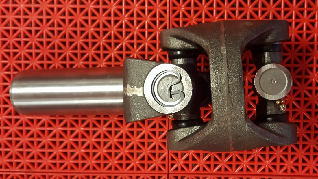
December 20, 2016
After the transmission components arrived, it was time to assemble and install the mock up drivetrain. I began by unpacking the new transmission and bell housing. I bolted them up to the old engine and maneuvered the whole thing into place with the engine hoist. The following time lapse video captures the 3-4 hours it took to do the job.
With the drivetrain roughly in place, I maneuvered it around until the driveshaft was properly engaged with both the transmission and differential, and the driveline angles were acceptable. I then trimmed down the 1/4" plate steel engine mount brackets that came with the kit I bought. When the fit was just right, I tack welded the brackets to the frame before removing the entire drivetrain so I could finish weld the brackets.
I noticed that this page is getting pretty long, so I've started another one to continue on. Look on the list of pages for Tom's Ramblings 2.
