January 6, 2017
I'll begin this page by acknowledging the obvious. I'm not likely to achieve my original goal of finishing the Cheetah by Spring 2017. My new goal is 2018.
The holidays and winter weather have slowed things a bit, but I'm still making progress. With the drivetrain in place I was able to finalize the placement of the brakelines, including the positions of the bulkheads where the lines leave the driver's footwell. That got me working on the clutch line and the throttle linkage. I won't be able finalize the postion of the clutch line bulkhead until I install the hydraulic throwout bearing (HTOB) and see where and how far the clutch line exits the transmission. But the portion in the footwell is done.
The Tilton 600 series floor mounted pedals that came with the car seem to be very well made. But the parts did not include the throttle linkage kit. This $120 part includes a mounting bracket, bell crank and linkage that converts the fore/aft motion of the pedal into the up/down motion needed to operate the throttle cable that will control the carburetor. The linkage kit didn't look that complicated to me so I decided to make my own. I drilled and tapped a block of aluminum for the bracket and fitted a bell crank and linkage pieces bought locally. I plan to cut down the aluminum block after I confirm that the position of the bell crank is good for the carburetor action. This video show the throttle action.
January 12, 2017
The challenge that has been nagging at me for some time is fitting the body to the rest of the car, especially the wheels and tires. My friend Bill dropped by a few days ago and helped me rest the body and nose back on the frame. I wasted a few very cold days getting just the right fasteners to attach the body to the frame. They had to have very thin "wafer" heads as some sit where the doors and nose overlay the main body. With the body mounted as it will be in the end, an unseasonably warm day today took away my last excuse for getting the fit right. But first, let me explain the challenge.
First, the fiberglass pieces for this car were hand laid using molds that were hand shaped. That means they are not perfectly symetrical and not ready for immediate use without some trimming, filling and minor modification. Second, the body was aligned to the frame by hand, so it may not be precisely level side-to-side, front-to-back or up and down. Third, the suspension has not had its final alignment and adjustment, so the wheels may not be precisely in their final positions. Fourth, I selected the largest wheels and tires I could fit on the car. That means there is very little clearance between the tires and body even when everything is perfectly fitted. Finally, as the load on the suspension increases, the frame (and body) will compress the springs and sit lower and closer to the tires. Up until now, the car has had nothing near the total weight it will carry when finished. That is where today's warm weather came into play.
I decided I needed 500-600 pounds of ballast in the cockpit to approximate the weight of two people, equipment that has not yet been installed, and a tank of gas. I eventually decided that my stash of leftover concrete blocks would be the best ballast. I estimate each block weighs about 30 pounds, so the eighteen I recovered from my back yard today and put where the seats go should have added about 540 pounds to the weight on the suspension. Here's what it looked like.
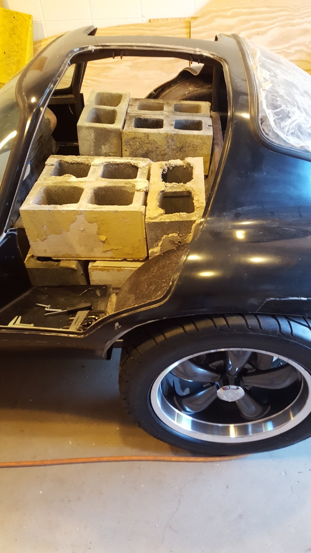
With the load in place, I discovered that the body fit very close to the tops of the tires. In fact, the front driver's side tire touched the body. I made some adjustments to the coilover shocks on the front to get a little more clearance, but it appears I will need to trim back the fiberglass body in a few places.
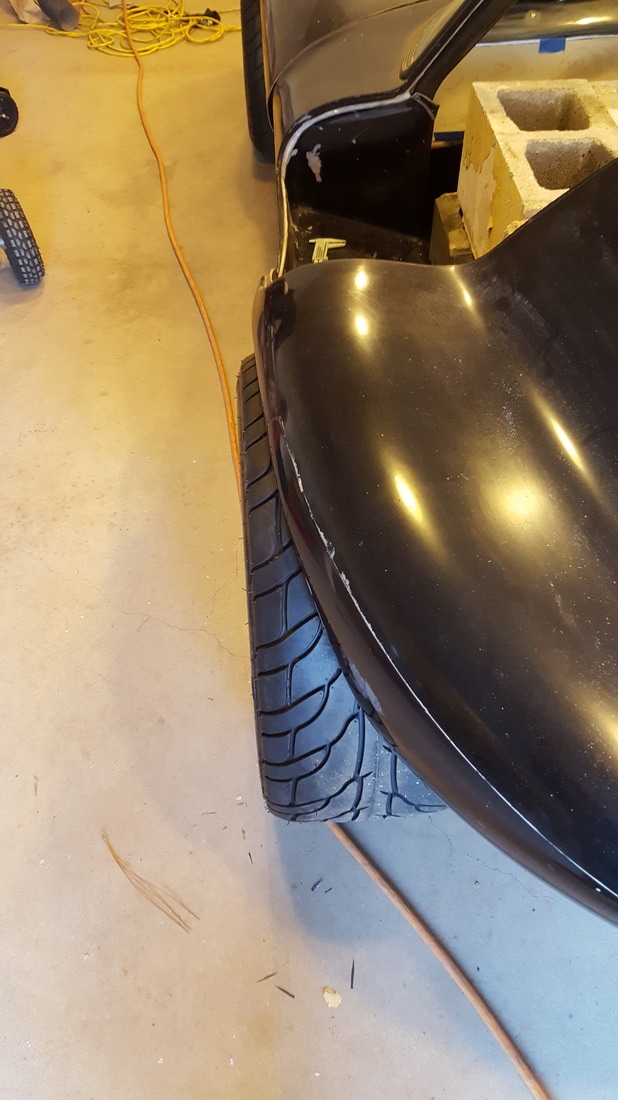
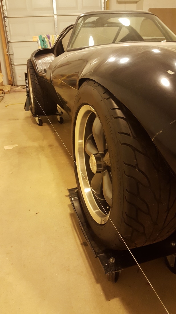
One of the things that became apparent with everything in place is that the rear tires are a little too wide for the body. I plan to fabricate some wider fender flares to make them fit better. This photo shows the "too wide" look in the rear.
One of the things that became apparent with everything in place is that the rear tires are a little too wide for the body. I plan to fabricate some wider fender flares to make them fit better. This photo shows the "too wide" look in the rear.
I'd like to take a moment here to say thanks to someone who has provided me with valuable insight into the task of working with a custom fiberglass body. But more importantly, he his has given me the courage to enthusiastically embrace the cutting, grinding, glassing and "its only fiberglass" attitude needed for the next stage of this project. I first met John Chesnut online on a forum for Shelby Cobra fans. John fabricates cars from scratch and enjoys many of the same obscure sports cars of the 1950-60s that I do. He is currently building a Cheetah roadster using his own frame and a hand laid fiberglass body inspired by but not identical to the original. He's been posting about his progress as he has shaped that body into what he wants it to be. He's progressing about ten times faster than me and that is good because it lets me learn more from him. .... John, if you read this, thanks a lot.
January 21, 2017
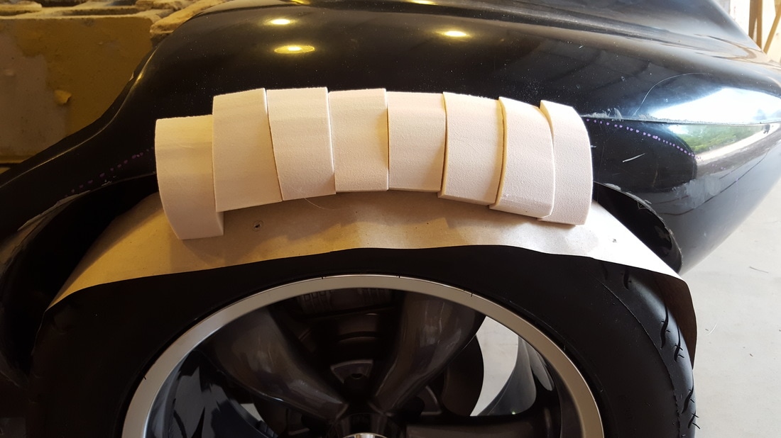
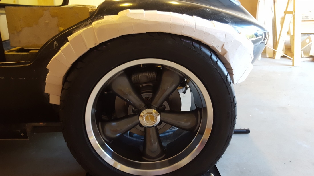
I began work on the fender flare for the left rear wheel about a week ago. Here are a few photos of my progress so far. The first step was cutting and attaching foam blocks that will be shaped to look like the new fender flare.
After all the foam blocks were in place, I used a rasp to achieve the general shape I wanted.
When the foam was about right, I topped it with body filler to fill any gaps and provide a surface for smoothing.
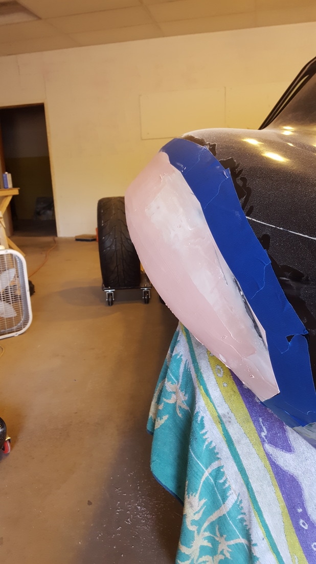
My plan was to have the top surface of this work match the exact contours I wanted on the top surface of the finished fender flare. That meant this foam structure would be the plug used to create a mold for the fender. In other words, I would make a fiberglass cast of this piece and then use that cast as the mold for the final fender. The advantage is that, if I did it right, the final fender would have a smooth, hard gel coat finish like the rest of the body.
The first step to achieving my goal was sanding the body filler smooth and filling any small holes. Several applications of body filler later, I accepted that I have neither the skill nor patience for body work. I decided to focus on getting the general shape of the fender flare right and let the body work experts who will paint and finish the body take care of making everything smooth. When things looked about right, I topped the body filler with primers, sanded it smooth and topped it with several coats of wax. Then I started making the mold by spreading gel coat over the wax.
The first step to achieving my goal was sanding the body filler smooth and filling any small holes. Several applications of body filler later, I accepted that I have neither the skill nor patience for body work. I decided to focus on getting the general shape of the fender flare right and let the body work experts who will paint and finish the body take care of making everything smooth. When things looked about right, I topped the body filler with primers, sanded it smooth and topped it with several coats of wax. Then I started making the mold by spreading gel coat over the wax.
On top of the gel coat I added a layer of fiberglass cloth, resin and additional cloth matting soaked in resin. I let it cure for two days and then tried to remove it. .... For the record, this is the first time I have done anything like this and I made several mistakes. For one, I didn't use enough of the right wax and I should have used a release agent as well. The end result is that the mold clung to the body filler and foam blocks when it was removed. I was able to remove them and sand the gel coat on the inside of the mold to a 150 grit quality finish, but it was not nearly as smooth as I hoped it would be. That means there will be even more work for the body shop guys.
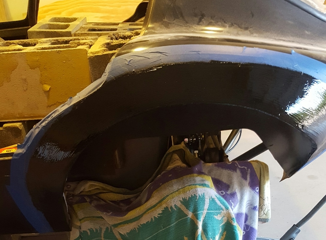
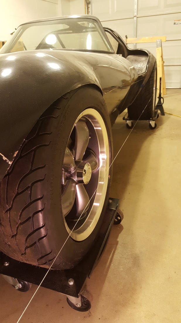
With the mold trimmed and cleaned up a bit, I used it to approximate the look of the finished fender flare. The next picture shows the unmodified passenger side of the car with the rear wheel protruding out beyond the fender. The picture after that show the driver's side with the modifed rear fender.
With the mold trimmed and cleaned up a bit, I used it to approximate the look of the finished fender flare. The next picture shows the unmodified passenger side of the car with the rear wheel protruding out beyond the fender. The picture after that show the driver's side with the modifed rear fender.
In the weeks since the last update I continued work on the fender flares when the weather cooperated. The mould for the passenger side fender flare is finished and I'll be making the flare for that side soon. When the weather wasn't right for body work, I began fabricating the front inner fender wells out of 0.05" aluminum sheets.
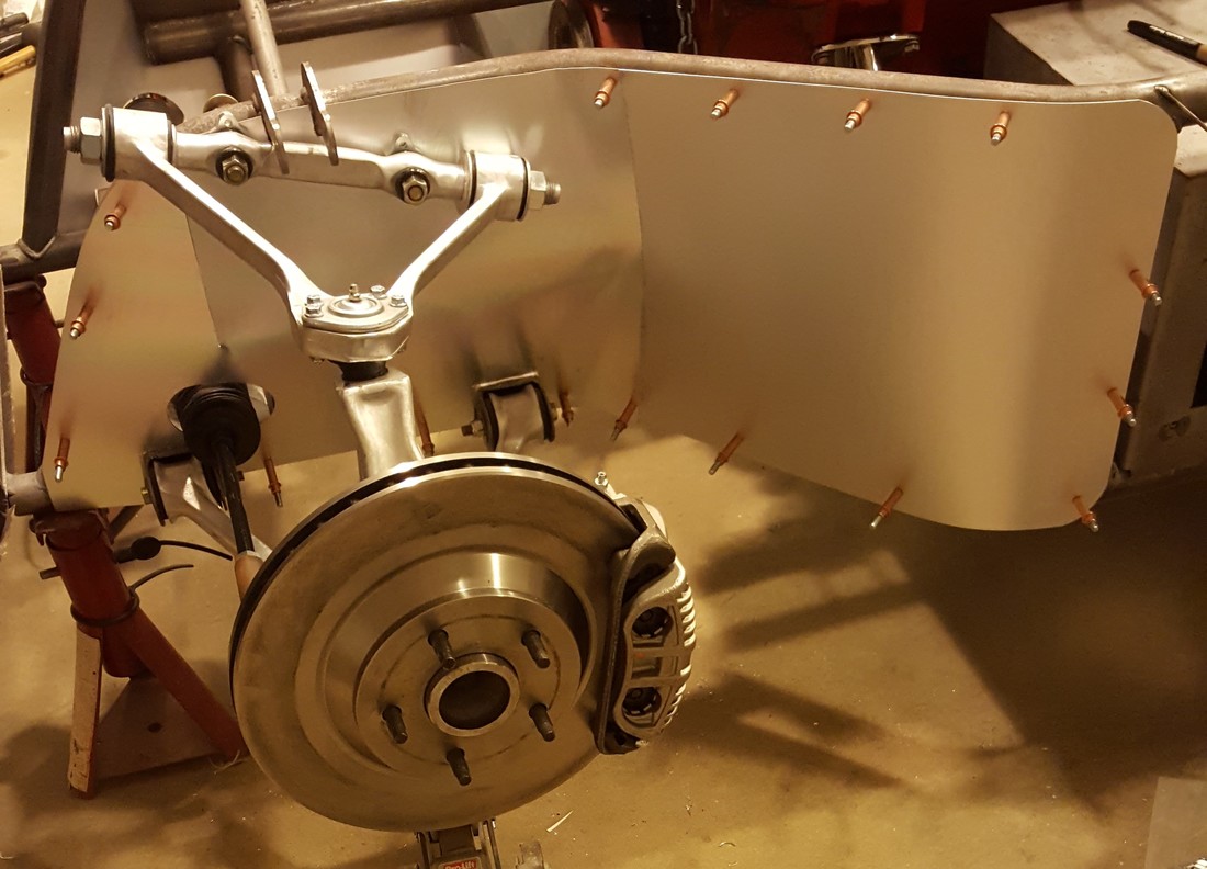
Each fender well is made with two pieces of aluminum that are attached to the tube frame. When the fiberglass front nose is tilted down into position, fiberglass braces that run from front to back on each side also serve to keep debris from the front wheels from splashing up into the top part of the engine compartment. The aluminum pieces overlap the nose pieces and keep debris out of the lower part of the engine compartment.
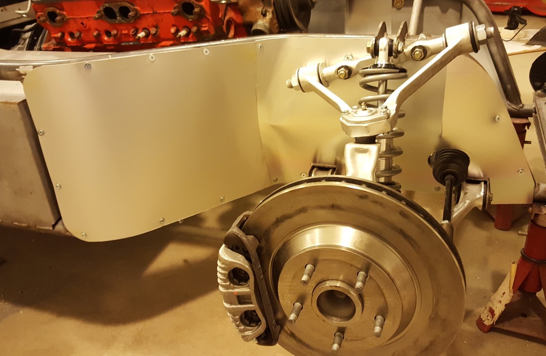
Fabricating each aluminum piece was a challengine and tedius process. This is because each piece requires multiple cuts and compound bends to fit around the front suspension. I started with poster paper templates, but they could not duplicate the radii of the aluminum sheets. So in the end it became a trial and error process. The first photo shows the driver's side wheel well as a work in progress with Cleco fasteners holding the pieces in place. The second photo shows the nearly finished passenger's side pieces. The final version will have black edge trim covering some of the exposed edges.
Each fender well is made with two pieces of aluminum that are attached to the tube frame. When the fiberglass front nose is tilted down into position, fiberglass braces that run from front to back on each side also serve to keep debris from the front wheels from splashing up into the top part of the engine compartment. The aluminum pieces overlap the nose pieces and keep debris out of the lower part of the engine compartment.
Fabricating each aluminum piece was a challengine and tedius process. This is because each piece requires multiple cuts and compound bends to fit around the front suspension. I started with poster paper templates, but they could not duplicate the radii of the aluminum sheets. So in the end it became a trial and error process. The first photo shows the driver's side wheel well as a work in progress with Cleco fasteners holding the pieces in place. The second photo shows the nearly finished passenger's side pieces. The final version will have black edge trim covering some of the exposed edges.
May 1, 2017
It's been months since I updated here, but I've been busy working on the Cheetah. Althought it may not sound like much, I've spent a lot of time working on the fit of the doors and nose. It's involved a lot of adding fiberglass and filler followed by sanding off most of it to get the various fiberglass pieces to fit better. A lot of that time was spent on the door edges where the inner and outer door shells were glued together. I had to get the door gaps close and shape the doors to fit the body openings. The inner door panel has to fit snug against the door flange to prevent leaks, and the outer door panel has to be level with body. There is still more to be done on this part of the project.
Part of aligning the doors and the nose is getting the hinges and spring loaded pneumatic supports positioned right. I first had to figure out where the ends of the supports go. Making them fit required fabricating tabs and welding them to the frame. While doing that I discovered that the hinge brackets for the driver's door were slightly lower than those on the passenger side. That limited the upward opening of the door and made the two side appear assymetrical when both doors were open. So I cut off and moved the driver's side brackets to solve the problem.
With the hinges and support rods in place, the last thing that determines the fit of the doors and nose is the latches. I spent many hours searching for the door latch mechanism that suited me. The Ohio shop typically uses latches intended for use in experimental aircraft. They look nice on the outside, but are somewhat complicated on the inside. And at about $600 a pair, I decided to go for something simpler and less expensive. I pieced together a system that I like for about $100. The final pieces are awaiting some machine shop work. I'll say more about them when I can add some photos.
Two other systems are also coming together. I ordered the custom radiator from AFCO. It is the one the Ohio shop typically uses. I've started on the radiator support system and will complete it as soon as the condensor for the air conditioner arrives for final fitting. I also ordered a custom fuel tank from RCI Racing. It arrived three days after we talked on the phone. I'm in the middle of fabricating the support brackets to hold it in place.
One challenge has taken many hours of thought and searching with no resolution - the air cleaner. Customarily the Cheetah has a hole in the hood for its carburetor or fuel injection system. This is because the car is so small the complete engine will not fit beneath the hood. It would be simple enough to put a large round air cleaner on the engine and cut a matching hole for it. But I'm hoping to have something different. .... The original Cheetah's ran Rochester mechanical fuel injection, so the piece sticking up through the hood was the rectangular finned aluminum plenum box. So I have been searching for an air cleaner that resembles that box, including sides that cover the filter element. So far I have not found the right air cleaner, so I may have to fabricate one to get the look I want. It's getting close to time for a final decision on this.
May 6, 2017
Building a custom car involves thousands of small decisions that will never be apparent to the observer of the finished car. Fortunately for me, the Internet has hundreds of photos of similar cars. Many of those photos tell me exactly what I need to know about a particular piece. However, there are not photos of every single detail. So in those areas I make my best guess.
When the radiator parts began to arrive, I started fabricating the four long steel rods that connect the top and bottom brackets that hold the radiator. The bottom bracket is tilted up in the front to pitch the top of the radiator back toward the rear of the car. I tack welded the first two rods to the bottom bracket being careful to space them to clear the radiator and mount them perpendicular to the bracket. I won't force you readers to go through the same hours of frustration that I went through, but here are the high points.
May 11, 2017
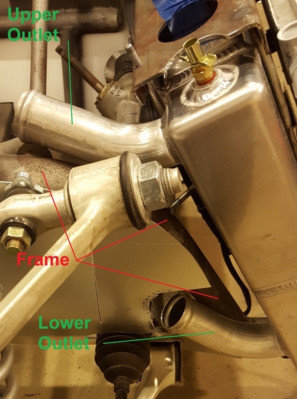
Here are some photos of the finished installation of the radiator and associated components. The first photo shows the tight fit between the radiator outlets and the frame rail.
It's been months since I updated here, but I've been busy working on the Cheetah. Althought it may not sound like much, I've spent a lot of time working on the fit of the doors and nose. It's involved a lot of adding fiberglass and filler followed by sanding off most of it to get the various fiberglass pieces to fit better. A lot of that time was spent on the door edges where the inner and outer door shells were glued together. I had to get the door gaps close and shape the doors to fit the body openings. The inner door panel has to fit snug against the door flange to prevent leaks, and the outer door panel has to be level with body. There is still more to be done on this part of the project.
Part of aligning the doors and the nose is getting the hinges and spring loaded pneumatic supports positioned right. I first had to figure out where the ends of the supports go. Making them fit required fabricating tabs and welding them to the frame. While doing that I discovered that the hinge brackets for the driver's door were slightly lower than those on the passenger side. That limited the upward opening of the door and made the two side appear assymetrical when both doors were open. So I cut off and moved the driver's side brackets to solve the problem.
With the hinges and support rods in place, the last thing that determines the fit of the doors and nose is the latches. I spent many hours searching for the door latch mechanism that suited me. The Ohio shop typically uses latches intended for use in experimental aircraft. They look nice on the outside, but are somewhat complicated on the inside. And at about $600 a pair, I decided to go for something simpler and less expensive. I pieced together a system that I like for about $100. The final pieces are awaiting some machine shop work. I'll say more about them when I can add some photos.
Two other systems are also coming together. I ordered the custom radiator from AFCO. It is the one the Ohio shop typically uses. I've started on the radiator support system and will complete it as soon as the condensor for the air conditioner arrives for final fitting. I also ordered a custom fuel tank from RCI Racing. It arrived three days after we talked on the phone. I'm in the middle of fabricating the support brackets to hold it in place.
One challenge has taken many hours of thought and searching with no resolution - the air cleaner. Customarily the Cheetah has a hole in the hood for its carburetor or fuel injection system. This is because the car is so small the complete engine will not fit beneath the hood. It would be simple enough to put a large round air cleaner on the engine and cut a matching hole for it. But I'm hoping to have something different. .... The original Cheetah's ran Rochester mechanical fuel injection, so the piece sticking up through the hood was the rectangular finned aluminum plenum box. So I have been searching for an air cleaner that resembles that box, including sides that cover the filter element. So far I have not found the right air cleaner, so I may have to fabricate one to get the look I want. It's getting close to time for a final decision on this.
May 6, 2017
Building a custom car involves thousands of small decisions that will never be apparent to the observer of the finished car. Fortunately for me, the Internet has hundreds of photos of similar cars. Many of those photos tell me exactly what I need to know about a particular piece. However, there are not photos of every single detail. So in those areas I make my best guess.
When the radiator parts began to arrive, I started fabricating the four long steel rods that connect the top and bottom brackets that hold the radiator. The bottom bracket is tilted up in the front to pitch the top of the radiator back toward the rear of the car. I tack welded the first two rods to the bottom bracket being careful to space them to clear the radiator and mount them perpendicular to the bracket. I won't force you readers to go through the same hours of frustration that I went through, but here are the high points.
- Photos show the upper radiator hose outlet fitting inside the frame rails. I assumed that meant the lower radiator outlet (which cannot be seen) also fit inside the frame rails. That was wrong. I had to hack a hole in my fresh aluminum fender well to find where the lower outlet would fit.
- Space between the radiator hose outlets and the frame rails is very tight, requiring the aft tilt of the radiator to be just so. It turns out the radiator is tilted more than the bottom bracket that supports it, so the rods I had welded into place had to be temporarily removed. It also means I will have to modify the way the radiator is supported on the bottom so the weight is evenly supported by the entire bottom surface of the radiator.
- I ordered the radiator with a very nice aluminum shroud and electric fan on the back. It turns out that won't fit the radiator brackets without removing parts of them.
- My car will have air conditioning so it must have a condensor mounted in front of the radiator. So the two remaining support rods had to have steel angle pieces welded to them to support the condensor.
May 11, 2017
Here are some photos of the finished installation of the radiator and associated components. The first photo shows the tight fit between the radiator outlets and the frame rail.
The next photo shows the radiator between the upper and lower mounts, the air conditioning condensor secured to its mounting rods, and the front electric fan, which is secured to the frame of the condensor. The rear fan and shroud is not easily seen.
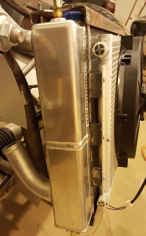
My goal was to have the radiator supported solely by rubber cushions between the radiator and the uppoer and lower support brackets. The only other thing touching the radiator is the rear shroud/fan assembly that was designed to attach to the perimeter frame of the radiator with screws. This should avoid leaks due to the lightweight aluminum rubbing against steel support pieces. The final test will be to refit the nose on the frame to be sure the rubber cushions have not raised the radiator assembly too much.
May 13, 2017
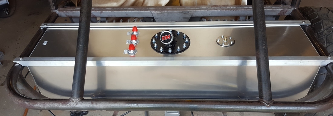
The supports for the fuel tank are finished. Here's what the 17 gallon tank looks like sitting snuggly between the frame rails. The fuel filler will connect to a flip top cap mounted just below the rear window in the center of the rear body.
(Post Script: some time after the above was written I learned this tank arrangement would not work. The filler neck is too far forward to allow fuel to easily flow from the body-mounted filler cap to the tank. I had another tank built with a wide top and narrow bottom to both fit in the space and move the filler neck as far back as possible.)
May 13, 2017
The supports for the fuel tank are finished. Here's what the 17 gallon tank looks like sitting snuggly between the frame rails. The fuel filler will connect to a flip top cap mounted just below the rear window in the center of the rear body.
(Post Script: some time after the above was written I learned this tank arrangement would not work. The filler neck is too far forward to allow fuel to easily flow from the body-mounted filler cap to the tank. I had another tank built with a wide top and narrow bottom to both fit in the space and move the filler neck as far back as possible.)
August 28, 2017
I tend to stay busy in my shops during the summer, so I haven't spent much time updating my progess here. But here is a short update.
The common thread to all my recent work has been prepping the fiberglass pieces to go for final body work and paint. That means I have been working on anything that either has to attach to the fiberglass or requires a hole in it. It also means I have been installing the gas struts that support the nose and both doors. The design of those pieces is such that they push on the doors and nose when they are closed. As that can move those fiberglass pieces slightly, I needed to have them in their correct final positions before aligning other pieces to them.
With the nose hung and supported I was able to accurately gauge the gap between the nose and the body. It was snug in some places so all it needed was a little final trimming. But in some other places the gap was wider than I wanted. Filling that gap on many car projects is as simple as adding some body filler (e.g., Bondo). But that wouldn't work for me and here is why.
When this particular Cheetah body was made, it was with hand laid the fiberglass body pieces. The technique created very lightweight body pieces that were only about 1/16" thick. For example, neither the nose or main body of my car weigh more than 50 pounds. The builder subsequently subcontracted production of the fiberglass pieces to another company and their items are much thicker, stiffer and heavier.
Working with the thin and very lightweight fiberglass panels poses three challenges. First, the body panels are very flexible and must be supported by other components of the car to maintain their shape. Second, the panels are so thin that grinding away material to make them fit better is not an option. I can never lower a high spot - I most fill and raise the adjoining low spot instead. Third, there is not enough edge thickness for ordinary body filler to grip when filling gaps. Instead I add additional fiberglass along the edge and then feather it to blend in with the existing panel. To make the panel thickness consistent, I had to add fiberglass along the entire width of the nose where it meets the body. As this is where the hood latches will attach to the hood, its just as well that I made the hood thicker (and stronger) in that area.
While I was working on the nose I noted that the people who attached the fiberglass stringers (long vertical panels that support and stiffen the hood) didn't do a great job. (OK, I was one of those people.) I spent several days grinding away the weak spots and adding new fiberglass in the joints to make things stronger and look better.
The next task on the nose was to cut holes in one of the stringers for the air conditioning lines that run from the condensor back to the engine compartment. The holes were elongated to account for the motion of the nose as it is raised and lowered. With the holes cut, another problem arose. The air conditioning hoses now pass through the right front wheel well and would be hit by road debris if not protected. The solution was to fabricate two custom fiberglass pieces that look like small air scoops. They will fit over the hoses and holes. I'll post pictures when they are installed.
The next item on my list was headlights. Here's what the headlight opening in the fender looks like. This photo shows it with a projector type headlight in an Internet car.
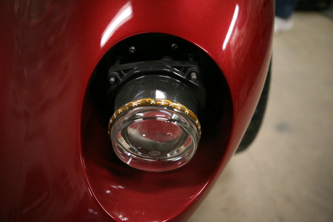
The opening is sized for a small (5-3/4") sealed beam as was used in the 1960s. I'm sure the projector beam is a big upgrade in terms of lighting, but I don't like the look of it. So I began a long search for the lighting equipment I wanted. Here are the challenges I had to overcome:
I spent many hours weighing the pros and cons of various options before deciding on the following combination of components:
- The unit had to fit within the 6" diameter opening in the fender.
- The unit needed to sit as far aft as an original style sealed beam.
- I needed a system to both secure the lights in place an allow for adjustment in directing the beams.
- Space behind the mounting face was limited due to the close proximity of the front tires.
- If any part of the light assemblies protruded aft of the mounting face, it would need to be protected from road debris from the front tires.
I spent many hours weighing the pros and cons of various options before deciding on the following combination of components:
- The lights will be 5-3/4" LED units designed for use in motorcycles. In addition to providing excellent lighting, each unit inclued HI and LOW beams, a partking light and a turn signal. This means I will not need to mount or wire separate parking lights or turn signal lights.
- Traditional chrome headlight retaining rings modified for my use.
- A custom fabricated PVC plastic ring with mounting screws.
The chrome retaining ring secures the headlight to the white plastic ring. Screws through the plastic ring go throught the headlight mounting face in the fender. Compression springs on each screw will allow the direction of the beam to be adjusted as nuts on each screw are tightened.
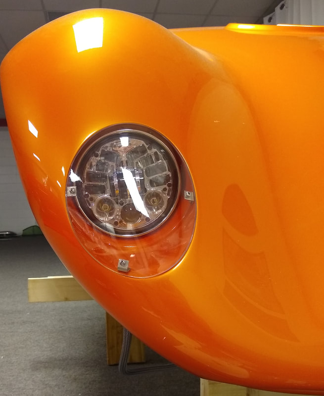
The LED light is about the same size as an old style sealed beam, so I had to cut a hole in the mounting face of the fender for it to fit. The back part of the light protrudes about 1-1/2" into the wheel well. That will not interfere with the tires, but it would expose the back of the light to road debris and rainwater if not protected. I fabricated custom fiberglass buckets to fit over the lights and secure to the existing fiberglass fender. LED lights do not run as hot as some headlights, but I will vent them to allow some air circulation and to allow any trapped moisture to escape.
If you look back at the photo of the headlight in the Internet car, you'll notice there is no clear cover over it. In fact, very few Cheetahs have headlight covers. But I wanted some. So I researched methods for using vacuum forming to shape clear plastic. As it turns out I have a very good friend who has access to vacuum forming equipment where he works. With that in mind, I purchased some 3/16" thick clear Lexan plastic and began work on plugs that will be used to shape the Lexan. The plugs are hard foam covered with body filler and topped with epoxy. The foam was shaped to fit the headlight opening and body filler was used to shape the plug to the contours of the surrounding fender. When the shape was right, the plug was coated with epoxy to provide a smooth surface for shaping the Lexan. This shows both plugs ready for the vacuum forming process.
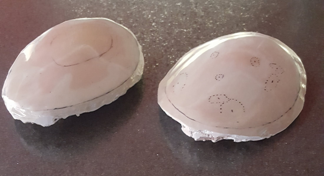
The black lines near the perimeter of each plug mark the edge of the finished headlight cover. The plugs were made slightly larger than that so the vacuum forming process would not produce a sharp bend in the Lexan at the edge. The other random markings are beneath the final coat of epoxy and indicate low areas that were filled during earlier stages of making the plugs.
September 13, 2017
I mentioned earlier about the pieces that will shield the air conditioning lines as they pass throught the right front wheel well. These photos show those two scoop shaped pieces mocked up in place on the fiberglass stringer panel. In both photos the nose is upside down on some stands with the viewer looking toward the front. The first photo shows the two pieces attached to the stringer. The second photo (from the engine's point of view) shows the holes the air conditioning lines will pass through before exiting the large opening as the back of the scoop shaped pieces. The holes and scoops are elongated so the nose will not rub on the fixed air conditioning lines as it is raised and lowered.
For the past week or so I have been working on fitting the nose to the body. The shape and location of the fiberglass body is determined by the way it was molded and by the steel framing that supports it. The shape and location of the nose is determined by four things - 1) the way it and the supporting fiberglass pieces that reinforce it were molded and fitted together; 2) the location and fitting of the hinge assembly that connects the nose to the frame at the bottom front; 3) the gas struts that support the hood when it is open; and 4) the location of four latches that secure the nose when it is closed. Most of the fitting work is done, but it has been tedious getting the last few high and low spots leveled out. I've had to pie-cut and reweld some of the steet framing to adjust the position of the body, and I had to do some trial and error fitting of the nose latches to get the fit near the firewall close enough to begin final body work. When that task is done I'll still have to fabricate supports for the fenders and lower body between the front wheels and the doors.
November 15, 2017
I've spent far more time thinking about what to do than actually doing much over the past two months. My quandry regarded getting all the fiberglass pieces ready for paint. The plain truth is I'm not very good at body work because I don't like doing it. But the local body shops, even those that routinely work with fiberglass, have not dealt with anything like this project. The body is so lightweight and thin that you must leave the windshields in place and bolt it to the frame to keep it rigid enough to work on. Even with that, there are places where it will flex while it is being worked. The shop most familiar with this car is in Ohio. I contacted them and they agreed to do the work needed to prep and paint the fiberglass pieces. My plan is to deliver the body and frame to them sometime in 2018. I hope to get it back with all the fiberglass pieces painted and ready for assembly.
With that major decision made, my new goal is to have the body ready to go to Ohio by spring. But that means many more decisions and much more work has to be done before then. Specifically, all the fiberglass pieces need to have all necessary holes or additions completed before final painting. For example, I had to finalize the layout of the gas tank and selection of the gas filler assembly so I'd know where and what size hole to cut for the filler. I'll also have to finalize my engine choice and install it to know what size and shape hole to cut in the nose for the air cleaner. So I have spent ten times as much time on my computer researching parts and sources as I have in the shop working on the project. Here is an example of why this process takes so long.
I have made a little physical progress in the shop. Here's a list:
On a topic only distantly related to the Cheetah project, I fulfilled a longtime goal two weeks ago when my nephew Robert and I attended the SEMA Show in Las Vegas. It was the most remarkable car show I have ever seen and is something every car guy should do at least once. I saw some interesting things that I may use on my car, and I was reminded just how much better the professional car builders are than me. But then for me, most of the fun is in working on the Cheetah, not just owning it.
May 31, 2018
Plainly I have neglected this blog for six months. It started with a lengthy illness during a colder than usual winter that discouraged me from working in the shop. But by March I was ready to continue my effort to have the Cheetah ready for final body work and paint by mid-2018. I soon realized I would have to have to install the real engine to finish my body preparations. For example, I'd need the headers fabricated and the location of the air cleaner to make final cuts in the fiberglass nose. And the first step to installing the real engine was deciding what engine I'd use.
I wrestled with the engine choice for several weeks. I relied heavily on the advice of family friend and respected race engine builder Bobby Hearn. My engine had to meet the following requirements:
I was happy with my decision to get this engine even though the builder was back ordered due to the coming racing season. I will not likely get the engine before late July, so my plans for delivering the body to Ohio will be delayed until later this year.
Slowed by the wait for the engine I used the good weather in April and May to do some chores that needed attention. That and some beautiful days with the family on Lake Martin meant I didn't get back to regular work on the Cheetah until this week. For now my attention is on being ready to assemble and install the drivetrain when the engine arrives. And I will then start the task of fabricating the headers. I'll go into that more when the time arrives.
July 12, 2018
In my effort to get the body ready for final work in Ohio, I decided to work on some things I will not want to do with the finished body in place. Several of those things involve fitting components like the HVAC, windshield wiper, gauges and wiring under the dash. Of those the two most challenging are the HVAC system and the windshield wipers. One way (perhaps the only way) to fit the HVAC control panel, ducting and air outlets is to add a center console between the transmission tunnel and the dash panel. I mocked up several center consoles to test the fit and look of ones made of steel and fiberglass. In the end I decided on a basic design but realized I could not finalize its dimensions until the interior upholstery is finalized. The console has to allow for the thickness of the upholstery on the transmission tunnel.
Fitting the windshield wiper system began by deciding where the wiper posts would pass through the body to put the wiper blades in the optimum positions on the windshield. The rest of the system consists of an electric motor that drives a gear that causes a long flexible cable to move out and back. Here's one example of an assembled system.
November 15, 2017
I've spent far more time thinking about what to do than actually doing much over the past two months. My quandry regarded getting all the fiberglass pieces ready for paint. The plain truth is I'm not very good at body work because I don't like doing it. But the local body shops, even those that routinely work with fiberglass, have not dealt with anything like this project. The body is so lightweight and thin that you must leave the windshields in place and bolt it to the frame to keep it rigid enough to work on. Even with that, there are places where it will flex while it is being worked. The shop most familiar with this car is in Ohio. I contacted them and they agreed to do the work needed to prep and paint the fiberglass pieces. My plan is to deliver the body and frame to them sometime in 2018. I hope to get it back with all the fiberglass pieces painted and ready for assembly.
With that major decision made, my new goal is to have the body ready to go to Ohio by spring. But that means many more decisions and much more work has to be done before then. Specifically, all the fiberglass pieces need to have all necessary holes or additions completed before final painting. For example, I had to finalize the layout of the gas tank and selection of the gas filler assembly so I'd know where and what size hole to cut for the filler. I'll also have to finalize my engine choice and install it to know what size and shape hole to cut in the nose for the air cleaner. So I have spent ten times as much time on my computer researching parts and sources as I have in the shop working on the project. Here is an example of why this process takes so long.
- Wiring for the headlight assemblies will have to pass through the fiberglass nose to reach controls under the dash. The size of the holes will depend on the routing, the number and size of wires and the loom that will cover them.
- Select wiring kit
- Consider number of circuits and size and placement of fuse panel
- Consider using relays to control high draw items
- Consider type and placement of relays and busbars
- Select wiring kit
I have made a little physical progress in the shop. Here's a list:
- Finalized the design for a fuel tank, had it built and installed it
- Selected a wiring assembly, fabricated a mount for the fuse panel and installed the panel
- Finalized the layout for gauges and switches in the dash
- Finalized the HVAC hose layout and mounted vents in the dash
- Fabricated and installed the tube that runs behind the seats to support the shoulder harnesses and headrests
- Fabricated a mount and installed the electric fuel pump
- Fabricated and installed floors and covers for two batteries in the engine compartment
- In order to place the batteries farther aft, I decided to use two smaller batteries connected in parallel rather than one larger battery
On a topic only distantly related to the Cheetah project, I fulfilled a longtime goal two weeks ago when my nephew Robert and I attended the SEMA Show in Las Vegas. It was the most remarkable car show I have ever seen and is something every car guy should do at least once. I saw some interesting things that I may use on my car, and I was reminded just how much better the professional car builders are than me. But then for me, most of the fun is in working on the Cheetah, not just owning it.
May 31, 2018
Plainly I have neglected this blog for six months. It started with a lengthy illness during a colder than usual winter that discouraged me from working in the shop. But by March I was ready to continue my effort to have the Cheetah ready for final body work and paint by mid-2018. I soon realized I would have to have to install the real engine to finish my body preparations. For example, I'd need the headers fabricated and the location of the air cleaner to make final cuts in the fiberglass nose. And the first step to installing the real engine was deciding what engine I'd use.
I wrestled with the engine choice for several weeks. I relied heavily on the advice of family friend and respected race engine builder Bobby Hearn. My engine had to meet the following requirements:
- As the State of Alabama requires complete records on the origin of the engine block, I decided to go with a brand new engine.
- I want the engine to resemble engines in the original Cheetahs so I decided to go with a first generation style Chevrolet small block engine.
- I want the engine to sound intimidating at idle like an old school race engine. So I decided to go with a large displacement engine with 10.5 to 1 compression.
- 427 cubic inch Dart Special High Performance Block
- All forged, name brand internals
- Air Flow Research aluminum heads, fully CNC ported
- Hydraulic roller cam and 1.5:1 roller rockers
- Victor Jr. aluminun mid-rise intake manifold
- Holley Ultra 850 carburetor
- Estimated peak torque 600 Lb-Ft and peak horsepower 600
I was happy with my decision to get this engine even though the builder was back ordered due to the coming racing season. I will not likely get the engine before late July, so my plans for delivering the body to Ohio will be delayed until later this year.
Slowed by the wait for the engine I used the good weather in April and May to do some chores that needed attention. That and some beautiful days with the family on Lake Martin meant I didn't get back to regular work on the Cheetah until this week. For now my attention is on being ready to assemble and install the drivetrain when the engine arrives. And I will then start the task of fabricating the headers. I'll go into that more when the time arrives.
July 12, 2018
In my effort to get the body ready for final work in Ohio, I decided to work on some things I will not want to do with the finished body in place. Several of those things involve fitting components like the HVAC, windshield wiper, gauges and wiring under the dash. Of those the two most challenging are the HVAC system and the windshield wipers. One way (perhaps the only way) to fit the HVAC control panel, ducting and air outlets is to add a center console between the transmission tunnel and the dash panel. I mocked up several center consoles to test the fit and look of ones made of steel and fiberglass. In the end I decided on a basic design but realized I could not finalize its dimensions until the interior upholstery is finalized. The console has to allow for the thickness of the upholstery on the transmission tunnel.
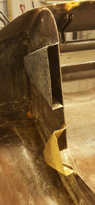
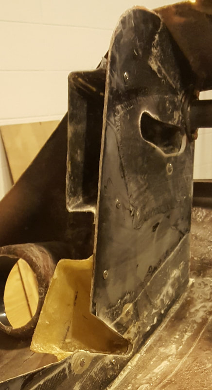
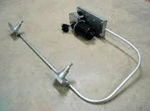
Fitting the windshield wiper system began by deciding where the wiper posts would pass through the body to put the wiper blades in the optimum positions on the windshield. The rest of the system consists of an electric motor that drives a gear that causes a long flexible cable to move out and back. Here's one example of an assembled system.
The cable slides inside an aluminum tube and engages gears at the bottom of each post assembly. As the cable slides back and forth, each post rotates to move the wiper blades. My first task was to find a place for the motor and gear assembly. To minimize stress that bends in the aluminum tube would place on the motor and cable I decided to place the motor in an unused space where the body flares out wide of the chassis to the right of the dash panel. It allows the tube from the motor to both posts be in a nearly straight line. To make it work I fabricated a sturdy bracket that attaches to the chassis to support the motor. With the posts secured to the thin fiberglass body and all the other pieces in place, I applied power to test the system. It was immediately obvious that the fiberglass flexed too much for the system to work. Consequently I designed and fabricated steel brackets I welded to the chassis at the firewall to anchor the wiper posts.
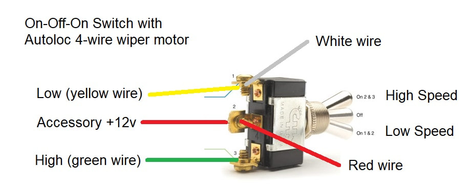
Another issue that took me a while to figure out was wiring the wiper motor with a toggle switch. I wanted to use a toggle switch for a consistent look on the dash but discovered there was little information on how to wire the Autoloc wiper motor to one. I offer the following to help any who may find this while looking for help.
The Autoloc wiper motor is relatively simple once you understand it. The motor is grounded through its mount and connected to the switch via four wires: red, white, yellow and green. Supplying +12v to the yellow wire runs the motor on low speed, and to the green wire runs high speed. The red and white wires work together to operate the PARK function so the wiper automatically returns to the parked position when the switch is turned OFF. The key to their operation is a mechanical switch within the motor assembly. The red wire should receive +12v any time the accessories are powered. The white wire receives power from the red wire through most of each cycle of the mechanical switch. But that power is removed briefly when the motor reaches the park position. By connecting the white wire to the yellow one, the motor continues to receive power when the switch is turned off until the mechanical switch reaches the park position. The following image shows how I wired my ON-OFF-ON toggle switch for the wipers.
A task that took a lot of my time in June was deciding where to get an exhaust system for the car. The picture above is an example of one builder's Cheetah exhaust. As can be seen, it consists of headers, a collector and bends, and a side exhaust (with or without heat shield.) My initial goal was to find someone local to build it for me. Plainly the builder would have to have the car in order to fit all the pieces in and around the existing components. I contacted, visited and spoke with about a half dozen prospective builders and found them either unavailable, inexperienced or frightfully expensive. Seeing no local builders that would work within my budget, I went back to the Internet and rediscovered a company called GPHeaders. Their niche is building affordable custom headers based on a mockup made by the owner using lightweight aluminum and PVC plastic components. My task will be to build a header system out of plastic, secure it with clamps and screws, and mail it back to GPHeaders. They will then build stainless steel headers that will fit in the same space as the plastic mock up. I ordered the mockup kit and will begin my part of the job when the engine is in place in the car.
Speaking of the engine, it is almost time for it to arrive. I have been gathering the parts and tools needed to install it in the chassis as soon as possible. Once it is in place I will be able to mock up the headers and finalize the selection of various other parts including the air cleaner and front accessory components.
September 5, 2018
The engine has not yet been shipped. For more on that story, see The Saga of the Engine Builder.
While waiting for the engine I have found a few small jobs to do, and I moved most of the project from the remote shop space I used to contain dust from metal and fiberglass work, to my main garage where the lift is located. It's a better organized space and the lift should make some aspects of the work more comfortable.
One project I have spent some time on is finishing the dash. The original piece was fiberglass. I've modified it some by removing some fiberglass, adding more in other places and drilling holes for gauges and switches. For the past few weeks I've been shaping and smoothing the surface in preparation for whatever finish I will use. My three options are to cover it in fabric such as black suede, or wrap it in vinyl to look like a carbon fiber piece, or to have it hydro dipped to look like carbon fiber. The first option would hide minor imperfections in the finish while the second option would require the surface to be smooth, but not perfect. The third option would require the surface to be prepped like a show quality paint job. I'm leaning toward the second option. My plan is to attempt my first ever vinyl wrap and see how it goes. If it does not look as good as I hope, I will reconsider my options.
October 18, 2018
My first attempt at doing a vinyl wrap was an unmitigated failure. I'm considering other options.
A lot has happened since the previous post and here are the highlights.
- The engine finally arrived.
- I assembled the engine, flywheel, clutch assembly, hydraulic throwout bearing, bell housing and transmission. This invoived a lot of lesser steps, e.g., checking the runout on the flywheel, but I will not list them as they are covered in numerous online videos by people more knowledgeable than me.
- I installed the engine/transmission in the car.
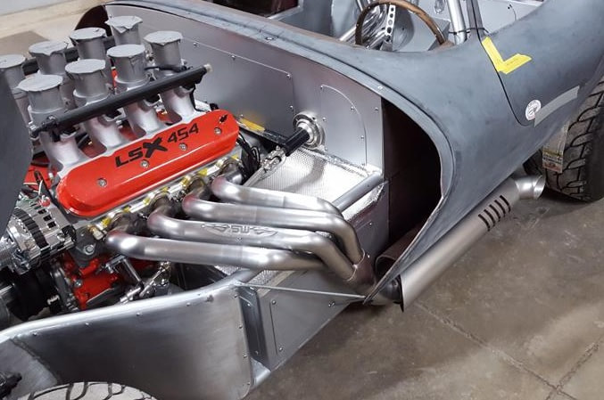
- I built a mockup of the header system using a kit obtained from GP Headers. Here are a few pictures of the mockup.
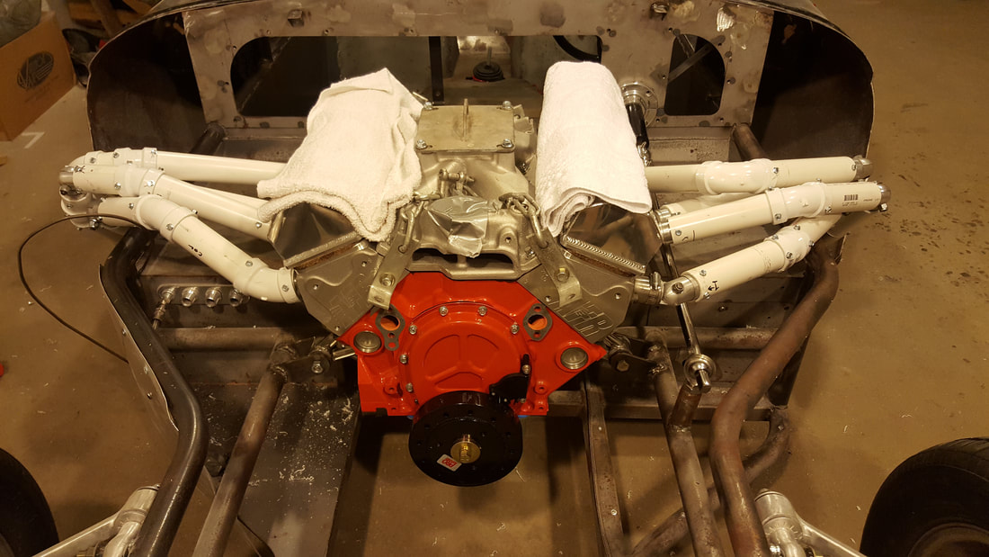
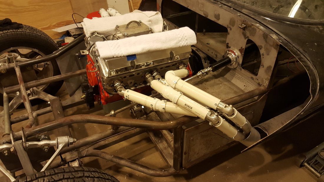
I shipped the finished mockups to GP Headers where they have built a set of stainless steel headers based on the critical dimensions of the mockups. They should arrive in a few days.
With the header designs done I began selecting and assembling the various accessories needed to complete the engine. They included:
While waiting for plumbing components to arrive, I began work on the wiring harness. My first goal was to detrmine where to place quick disconnects so the nose and body could be easily removed if/when that becomes necessary. My second goal was to keep the wiring organized while making the final assembly as easy as possible (e.g., no upside down soldering under the dash). I will be making use of a large number of waterproof quick connects that lock into place. Of course accomplishing my goals meant sorting out the wiring harness and understanding how each electrical component had to be wired. It has been a time consuming and tedious process.
As work progressed I realized I should move the assembly operation from the small room where the car has been for a few years, to the large garage when my lift is located. I had avoided that before because much of the work involved both grinding metal and sanding body filler and fiberglass. I did not want that mess in my much nicer big garage. So I used the small room one last time to install the engine and transmission, and then I moved the car onto the lift. Let me tell you that the lift has greatly extended the useful garage life of this old amatuer mechanic. That car has got far more vertical miles (or feet) on it than horizontal. And my body is extremely grateful.
Much of the work I've done while waiting for the headers to arrive is work that needed to be done eventually, but not right now. But that will change when the headers arrive. My goal is to deliver the car (body, chassis and engine) to Ohio next month so they can do the final body work and painting of the fiberglass pieces. He'll want the engine and headers in place to better fit the body. I hope to have the rest of the exhaust system including the side pipes also finished and in place when I deliver the car. So I've ordered the side pipe components and lined up two welders to finish the exhaust system locally.
November 9, 2018
I delivered the car to Ohio for finish body work, paint and a few other things. While there we discussed two things that will affect how the nose will look. This picture of a modified Cheetah will make it easier to visualize.
With the header designs done I began selecting and assembling the various accessories needed to complete the engine. They included:
- Crankshaft pulley
- Waterpump and pulley
- Alternator, bracket and pulley
- AC compressor and bracket
- Belts to drive the accessories
- Fuel lines
- Water neck filler and thermostat housing
- Upper and lower radiator hoses, connectors and clamps
- Heater hoses and fittings
- BTW, I discovered that there is a small adapter needed to attach a standard -10AN fitting to a #10 AC fitting as on my bulkhead. I spent three hours searching and talking with three Technical Advisors, none of whom knew how to mate the two fittings. I subsequently discovered 4 Seasons part # 16749 which does the job.
- HVAC hoses and fittings
- I spent hours searching for a reasonably priced alternative to the drab black HVAC hoses and fittings used on 99.9% of cars. All I coud find was an Aeroquip system that costs about $120-150 per hose for a total of near $600. I went drab.
While waiting for plumbing components to arrive, I began work on the wiring harness. My first goal was to detrmine where to place quick disconnects so the nose and body could be easily removed if/when that becomes necessary. My second goal was to keep the wiring organized while making the final assembly as easy as possible (e.g., no upside down soldering under the dash). I will be making use of a large number of waterproof quick connects that lock into place. Of course accomplishing my goals meant sorting out the wiring harness and understanding how each electrical component had to be wired. It has been a time consuming and tedious process.
As work progressed I realized I should move the assembly operation from the small room where the car has been for a few years, to the large garage when my lift is located. I had avoided that before because much of the work involved both grinding metal and sanding body filler and fiberglass. I did not want that mess in my much nicer big garage. So I used the small room one last time to install the engine and transmission, and then I moved the car onto the lift. Let me tell you that the lift has greatly extended the useful garage life of this old amatuer mechanic. That car has got far more vertical miles (or feet) on it than horizontal. And my body is extremely grateful.
Much of the work I've done while waiting for the headers to arrive is work that needed to be done eventually, but not right now. But that will change when the headers arrive. My goal is to deliver the car (body, chassis and engine) to Ohio next month so they can do the final body work and painting of the fiberglass pieces. He'll want the engine and headers in place to better fit the body. I hope to have the rest of the exhaust system including the side pipes also finished and in place when I deliver the car. So I've ordered the side pipe components and lined up two welders to finish the exhaust system locally.
November 9, 2018
I delivered the car to Ohio for finish body work, paint and a few other things. While there we discussed two things that will affect how the nose will look. This picture of a modified Cheetah will make it easier to visualize.
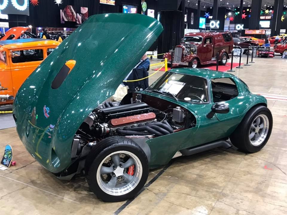
On most Cheetahs, all the fiberglass forward of the firewall is a single piece called the nose. Like this car, my car will have the "wings" (pieces directly behind the front wheels) separated from the tilt nose. This makes the task of opening and closing the nose a one man job. Because the nose is wide at the beltline and much narrower near the ground, without this modification one either has to get help every time or install a large and unsightly guide piece that pushes the wings outward when they are lowered. This will make my non-authentic Cheetah slightly more non-authentic, but it will make it much easier when people want to take a look at the engine compartment.
The other change to the nose involves the hole where the air cleaner protrudes through the nose. That hole weakens the already very thin fiberglass and would allow the nose to flex at higher speeds. The shop will address this by adding strengthening strips to the underside of the nose and by incorporating a small lip around the perimeter of the hole.
The most exciting part of this phase for me is selecting the paint color. I want an uncommon color that recalls the outrageous colors of the slot car toy Cheetahs of long ago. I'm leaning toward an orange that shows flashes of gold in sunlight. The first sample I liked turned out to cost $2,300 per gallon. Yikes! So my goal is to find something I really like that is more affordable.
As I plan to spend December and January in south Florida avoiding Alabama's cold, wet winter, I told the shop working on the car that I would pick it up when the snow melted in Ohio. He predicted it would be ready by March 2019.
February 20, 2019
I returned to my home in Alabama earlier this month. While I was living in my motorhome in Florida, I spent some time mentally reviewing all the things I would be doing when I got the car back painted. The tasks fell into several phases.
May 9, 2019
The Ohio shop has had the car for six months and there is still much he needs to do. We talked and he explained that he had been swamped by other tasks, some of which were not predictable. He assured me that my car would be ready by June 2019.
My major task while waiting for him to complete the body work was deciding on the paint for the exterior. My main goal was to have an uncommon color that was reminiscent of the slot car Cheetah toys familiar to many people my age. Eventually I settled on a shade of orange that flashes gold in the sunlight. This youtube video was my inspiration. It turned out this paint goes for $2,300 per gallon! I rethought my options and began to learn a lot more about custom car paints.
I learned most of what I know about paint from Dub, the highly regarded owner of a Corvette specialty auto repair shop in North Carolina. Here are the highlights.
September 12, 2019
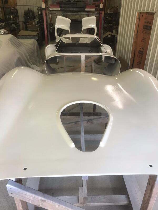
The Ohio shop has missed two more completion dates but appears close to making his most recently promised September 30 date. Most of the body work is complete and all the fiberglass body pieces are now in white gelcoat. Following a bit more work and painting of some underside surfaces, it should go to the painter in a few days. Here's what the body looks like now.
The other change to the nose involves the hole where the air cleaner protrudes through the nose. That hole weakens the already very thin fiberglass and would allow the nose to flex at higher speeds. The shop will address this by adding strengthening strips to the underside of the nose and by incorporating a small lip around the perimeter of the hole.
The most exciting part of this phase for me is selecting the paint color. I want an uncommon color that recalls the outrageous colors of the slot car toy Cheetahs of long ago. I'm leaning toward an orange that shows flashes of gold in sunlight. The first sample I liked turned out to cost $2,300 per gallon. Yikes! So my goal is to find something I really like that is more affordable.
As I plan to spend December and January in south Florida avoiding Alabama's cold, wet winter, I told the shop working on the car that I would pick it up when the snow melted in Ohio. He predicted it would be ready by March 2019.
February 20, 2019
I returned to my home in Alabama earlier this month. While I was living in my motorhome in Florida, I spent some time mentally reviewing all the things I would be doing when I got the car back painted. The tasks fell into several phases.
- Cleaning, painting and prepping parts still here in my garage.
- Retrieve the car.
- Doing tasks that must be finished before the chassis goes for powder coating.
- Disassembling the car.
- Having the chassis and metal parts cleaned and powder coated.
- Insulating the cockpit.
- Partially reassembling the car.
- Having the interior installed.
- Finishing the assembly.
- Obtaining a title and registration.
May 9, 2019
The Ohio shop has had the car for six months and there is still much he needs to do. We talked and he explained that he had been swamped by other tasks, some of which were not predictable. He assured me that my car would be ready by June 2019.
My major task while waiting for him to complete the body work was deciding on the paint for the exterior. My main goal was to have an uncommon color that was reminiscent of the slot car Cheetah toys familiar to many people my age. Eventually I settled on a shade of orange that flashes gold in the sunlight. This youtube video was my inspiration. It turned out this paint goes for $2,300 per gallon! I rethought my options and began to learn a lot more about custom car paints.
I learned most of what I know about paint from Dub, the highly regarded owner of a Corvette specialty auto repair shop in North Carolina. Here are the highlights.
- The number of color coats required depends on the under color and the type of color paint being used. Test sprays with a black/white card will reveals how many coats are needed.
- Paints with additives like pearl (glass beads) and metallic (metal flakes) require special attention to turn out well. They are also hard to match for later repairs.
- The paint must be well mixed immediately before it is sprayed because the solids will settle over time causing uneven distribution.
- Parts being sprayed should be oriented the same as they will be on the finished car (e.g., the doors should be vertical and not flat).
- On the final color coat, the entire car should be sprayed from one batch to assure consistent color on pieces when the car is put back together.
- Some of the best looking custom paint jobs involve multiple paint coats. For example, there may be a solid color base coat (e.g., gold) followed by several thin layers of a pearl coat (e.g., orange), and tinted clear coats. This allows color elements of three different paints to influence the final appearance. These types of paint jobs are very expensive and near impossible to repair.
September 12, 2019
The Ohio shop has missed two more completion dates but appears close to making his most recently promised September 30 date. Most of the body work is complete and all the fiberglass body pieces are now in white gelcoat. Following a bit more work and painting of some underside surfaces, it should go to the painter in a few days. Here's what the body looks like now.
When the body gets back to my shop, there will still be much to do before it will be ready for final assembly. Here are some of the major tasks:
January 26, 2020 (Reality intrudes on my optimistic hopes)
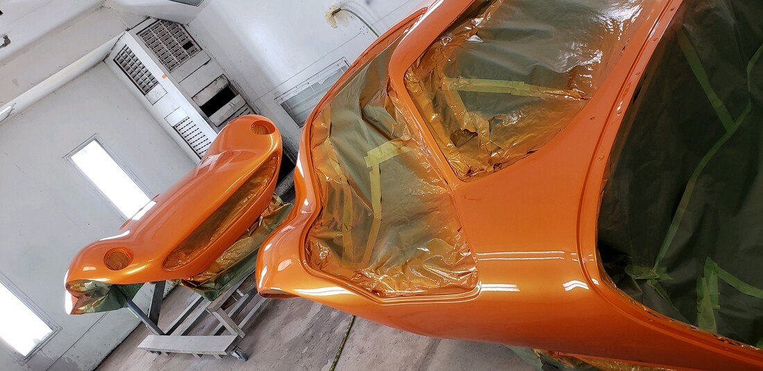
People who seek custom paint for their cars sometimes speak of "body shop prison." Its a euphemism for the apparent fact that body shops and painters often take far longer to complete a custom job than the estimate they gave when securing the job. That was my experience as the job that I expected to take five months has stretched into thirteen months. But the good news today is that the painting is essentially complete. When I get the official word that the exterior paint is completed, I'll drive to Ohio to speed up the work and help put the body back on the chassis and finish it up for the trip back home. For now, here is a photo of the body and nose in the paint booth.
- Finalize plans for the upholstery and choose a shop for the job.
- Finalize decisions regarding the placement of dozens of small items (e.g., horn, battery cutoff switch, etc.).
- Finalize decisions regarding the valve covers and PCV system.
- Fabricate custom baffles (i.e., mufflers) for the side pipes.
- Send exhaust system off for ceramic coating.
- Remove and store the body pieces.
- Replace the oil pan with one that fits the chassis better.
- Remove everything from the chassis.
- Finish remaining welding and fabrication on the chassis.
- Deliver the chassis and other metal parts for blasting and powder coating.
- When the chassis returns, insulate it inside and out.
January 26, 2020 (Reality intrudes on my optimistic hopes)
People who seek custom paint for their cars sometimes speak of "body shop prison." Its a euphemism for the apparent fact that body shops and painters often take far longer to complete a custom job than the estimate they gave when securing the job. That was my experience as the job that I expected to take five months has stretched into thirteen months. But the good news today is that the painting is essentially complete. When I get the official word that the exterior paint is completed, I'll drive to Ohio to speed up the work and help put the body back on the chassis and finish it up for the trip back home. For now, here is a photo of the body and nose in the paint booth.
February 2, 2020
Consider what follows as advice for those who would choose the paint called Atomic Orange. I asked the shop to inspect the finished paint job before I started my long drive from Alabama to Ohio to pick up the car. When I got his approval, I made the drive. On arrival I was told "there is a minor problem with the paint." It turned out that they had inspected the paint before it was cut and buffed, and did not notice a flaw the painter subsequently noticed. In his effort to rush the job to avoid disappointing me, the painter resprayed an area the size of a dinner plate. When it dried it did not match the surrounding paint .... just as I had warned him. To his credit, the painter acknowledged his error and set about repainting the entire car to get the paint right. Of course that added days to my trip - a minor inconvenience compared to the fifteen months I had already waited. But it was more than a minor inconvenience and cost to the painter. This paint is much less forgiving of error than most base coat / clear coat finishes.
February 6, 2020
Back from Ohio with the car still in the trailer I can say that the color and quality of the paint job are spectacular - a tribute to the skil and dedication of the painter. The rest of the experience was dismal as much of the work I had paid to have done was not completed. Faced with the choice of waiting for many more days with a mounting hotel bill, I opted to take the car as is and finish the work myself.
February 13, 2020
With the car out of the trailer and after many hours of looking it over I have come to fully grasp the scope of the work I paid for that was not done. If you refer back to my post of November 9, 2018 you'll note that I opted for the split nose feature done by the shop on another Cheetah. This was offered as a way to make it possible for a single person to open and close the nose, and to avoid the unsightly guide rods needed for the single piece nose. What I learned while retrieving my car is that the split nose work on the previous car was never completely worked out to achieve a good fit. That issue has still not been worked out and it is up to me to figure it out WHILE WORKING ON PAINTED PARTS! For example, I will need some kind of latching system where the upper nose meets the lower pieces to get them to align. That work should have been done before the painting was done, but it wasn't. In addition, the nose is mounted about 1/4" offset to one side, so the hinge system will need work. And the contour of the nose where it meets the body at the firewall is not good. I will try to correct it without damaging the finished paint job.
Other major work that was promised but not delivered was fabricating and installing the rear shelf that sits beneath the rear window, and fabricating and installing panels that fill the gaps between the body and chassis at the firewall. I was provided the materials for this work, but I will have to do all the labor myself. Like the work that should have been done on the nose, this work could have and should have been completed BEFORE the car went to paint.
If you have been paying attention you may have noticed a pattern in the events of the past month. That pattern will become more clear when I add one more fact. In mid December 2019 I told the shop that my patience had ended and hinted at legal action if the car was not completed by the end of January 2020. Their failure to fully assemble the completed body parts before painting, their failure to fully inspect the completed paint job BEFORE telling me it was ready, and the painter's rush to finish the job which resulted in him having to repaint the entire car while I waited, all arose because they had not used the previous thirteen months effectively. Thus they did an incomplete job. And even that wouldni't have happened if I had not threatened legal action AND camped out nearby until I had the car in my trailer. I will never do business with that shop again.
February 25, 2020
While my anger at the shop that screwed me bubbles up from time to time, overall I have been very happy to have the Cheetah back in my garage where I can work on it. I've mde many decisions regarding the placement of peripheral parts (e.g., coolant catch can and third brake light) and I took it to the upholstery shop so they could start working up a quote for doing the interior. I've even started on the ten or so pieces of aluminum that will form the shelf behind the seats. But not suprisingly, the most time consuming tasks have involved parts I didn't expect to be that challenging.
I've had the car on shop wheels for a long time to protect the good ones. But I needed to see how it looked on the finished body and I needed to select the right lug nuts to complete the look. The wheels look good, but lug nuts turned out to be a challenge. Here is a summary of the issues:
Another issue that took far more time than I hoped was selecting a battery. The ideal location is in the engine compartment but in an area shielded from the heat. The most likely place (forward of the footboxes) is too small for a conventional battery, but there are two of these areas. Without exaggeration, I spent at least forty hours researching the pros and cons of every type of battery that could provide both the starting power (cranking amps) and duration (amp hours) required. I discovered than some could be linked, allowing multiple batteries, and some could be mounted on their sides to fit better in tight spaces. And I learned an immense amount about lithium iron phosphate batteries that are very light and very expensive. Near the end of my search I planned to fit three absorbed glass mat batteries in the two spaces, but came up 1/16" short. So I'll end up doing what every other car like mine has done - put a conventional battery in the space between the radiator and engine. I'm still working on a method of protecting it from the heat, but it seems the only option.
The last task that has consumed much of my time has been working out the design for a system to make raising and lowering the nose safer and easier. As I mentioned earlier, the whole point of going with the split nose was to make it easier for a single person to open it. While the shop's work reduced the weight of the nose some by separating the "wings" behind the wheels, they more than offset that by adding reinforcement to stiffen the nose around the opening for the engine. The result is I have the choice of yanking my fingers from the closing nose and have the nose crash down into place, or leave them until the last moment and risk losing them. Similarly, I have to raise one side of the nose enough to insert an expendable finger to get a grip to open it.
Faced with this unacceptable situation, I started looking at ways to power the nose up and down. There are many challenges and I settled on a design using linear actuators to raise the nose about six inches to where I could safely grasp it and raise it all the way up. Going down the nose will rest on the extended actuator rods until it is lowered all the way down. The biggest question is how to engage and disengage the nose from the actuator rods. Over a period of five days I sketched out five systems, each a little better than the one before. After many hours of thinking and sketching I was confident enough to order a pair of actuators. I'll soon know if my last design will work.
March 28, 2020
The theme for today's post is this. Nothing is all good or all bad. There is bad in the best of things and good in the worst of things. .... But I'll start where I left off with the actuators.
When the actuators arrived I held them where I imagined they would fit and saw that my latest design should work. The first test was to modify both the top and bottom mounts. As the picture below shows, the top of the rod now has a vertical threaded hole for the pin that will engage the latch on the nose. And the bottom mount has a new hole drilled so the actuator can sit closer to the firewall. All that remained was fabricating a bracket to support the bottom of the actuator and allow the height to be adjusted to get the nose to fit correctly. The bracket will be welded to the firewall later. All of the threaded pieces in the photo are too long and will be trimmed to fit during actual assembly.
Consider what follows as advice for those who would choose the paint called Atomic Orange. I asked the shop to inspect the finished paint job before I started my long drive from Alabama to Ohio to pick up the car. When I got his approval, I made the drive. On arrival I was told "there is a minor problem with the paint." It turned out that they had inspected the paint before it was cut and buffed, and did not notice a flaw the painter subsequently noticed. In his effort to rush the job to avoid disappointing me, the painter resprayed an area the size of a dinner plate. When it dried it did not match the surrounding paint .... just as I had warned him. To his credit, the painter acknowledged his error and set about repainting the entire car to get the paint right. Of course that added days to my trip - a minor inconvenience compared to the fifteen months I had already waited. But it was more than a minor inconvenience and cost to the painter. This paint is much less forgiving of error than most base coat / clear coat finishes.
February 6, 2020
Back from Ohio with the car still in the trailer I can say that the color and quality of the paint job are spectacular - a tribute to the skil and dedication of the painter. The rest of the experience was dismal as much of the work I had paid to have done was not completed. Faced with the choice of waiting for many more days with a mounting hotel bill, I opted to take the car as is and finish the work myself.
February 13, 2020
With the car out of the trailer and after many hours of looking it over I have come to fully grasp the scope of the work I paid for that was not done. If you refer back to my post of November 9, 2018 you'll note that I opted for the split nose feature done by the shop on another Cheetah. This was offered as a way to make it possible for a single person to open and close the nose, and to avoid the unsightly guide rods needed for the single piece nose. What I learned while retrieving my car is that the split nose work on the previous car was never completely worked out to achieve a good fit. That issue has still not been worked out and it is up to me to figure it out WHILE WORKING ON PAINTED PARTS! For example, I will need some kind of latching system where the upper nose meets the lower pieces to get them to align. That work should have been done before the painting was done, but it wasn't. In addition, the nose is mounted about 1/4" offset to one side, so the hinge system will need work. And the contour of the nose where it meets the body at the firewall is not good. I will try to correct it without damaging the finished paint job.
Other major work that was promised but not delivered was fabricating and installing the rear shelf that sits beneath the rear window, and fabricating and installing panels that fill the gaps between the body and chassis at the firewall. I was provided the materials for this work, but I will have to do all the labor myself. Like the work that should have been done on the nose, this work could have and should have been completed BEFORE the car went to paint.
If you have been paying attention you may have noticed a pattern in the events of the past month. That pattern will become more clear when I add one more fact. In mid December 2019 I told the shop that my patience had ended and hinted at legal action if the car was not completed by the end of January 2020. Their failure to fully assemble the completed body parts before painting, their failure to fully inspect the completed paint job BEFORE telling me it was ready, and the painter's rush to finish the job which resulted in him having to repaint the entire car while I waited, all arose because they had not used the previous thirteen months effectively. Thus they did an incomplete job. And even that wouldni't have happened if I had not threatened legal action AND camped out nearby until I had the car in my trailer. I will never do business with that shop again.
February 25, 2020
While my anger at the shop that screwed me bubbles up from time to time, overall I have been very happy to have the Cheetah back in my garage where I can work on it. I've mde many decisions regarding the placement of peripheral parts (e.g., coolant catch can and third brake light) and I took it to the upholstery shop so they could start working up a quote for doing the interior. I've even started on the ten or so pieces of aluminum that will form the shelf behind the seats. But not suprisingly, the most time consuming tasks have involved parts I didn't expect to be that challenging.
I've had the car on shop wheels for a long time to protect the good ones. But I needed to see how it looked on the finished body and I needed to select the right lug nuts to complete the look. The wheels look good, but lug nuts turned out to be a challenge. Here is a summary of the issues:
- Wheels studs on the front and rear are different lengths
- Fornt and rear wheels are different sizes meaning the lugs are more deeply recessed on the rear
- There are multiple nut shapes and only the 60 degree conical bulge shape will work
- Capped (closed end) nuts have to be long enough to fit over the entire exposed studs
- Open nuts offer more flexibility for fitting over studs, but most of them readily available are made of aluminum (not suitable for my car)
- The ideal nut length that would work for front and rear is 1.6 inches
- The only nuts I found in that size are stainless steel Australian racing nuts for about $250 a set plus shipping!
Another issue that took far more time than I hoped was selecting a battery. The ideal location is in the engine compartment but in an area shielded from the heat. The most likely place (forward of the footboxes) is too small for a conventional battery, but there are two of these areas. Without exaggeration, I spent at least forty hours researching the pros and cons of every type of battery that could provide both the starting power (cranking amps) and duration (amp hours) required. I discovered than some could be linked, allowing multiple batteries, and some could be mounted on their sides to fit better in tight spaces. And I learned an immense amount about lithium iron phosphate batteries that are very light and very expensive. Near the end of my search I planned to fit three absorbed glass mat batteries in the two spaces, but came up 1/16" short. So I'll end up doing what every other car like mine has done - put a conventional battery in the space between the radiator and engine. I'm still working on a method of protecting it from the heat, but it seems the only option.
The last task that has consumed much of my time has been working out the design for a system to make raising and lowering the nose safer and easier. As I mentioned earlier, the whole point of going with the split nose was to make it easier for a single person to open it. While the shop's work reduced the weight of the nose some by separating the "wings" behind the wheels, they more than offset that by adding reinforcement to stiffen the nose around the opening for the engine. The result is I have the choice of yanking my fingers from the closing nose and have the nose crash down into place, or leave them until the last moment and risk losing them. Similarly, I have to raise one side of the nose enough to insert an expendable finger to get a grip to open it.
Faced with this unacceptable situation, I started looking at ways to power the nose up and down. There are many challenges and I settled on a design using linear actuators to raise the nose about six inches to where I could safely grasp it and raise it all the way up. Going down the nose will rest on the extended actuator rods until it is lowered all the way down. The biggest question is how to engage and disengage the nose from the actuator rods. Over a period of five days I sketched out five systems, each a little better than the one before. After many hours of thinking and sketching I was confident enough to order a pair of actuators. I'll soon know if my last design will work.
March 28, 2020
The theme for today's post is this. Nothing is all good or all bad. There is bad in the best of things and good in the worst of things. .... But I'll start where I left off with the actuators.
When the actuators arrived I held them where I imagined they would fit and saw that my latest design should work. The first test was to modify both the top and bottom mounts. As the picture below shows, the top of the rod now has a vertical threaded hole for the pin that will engage the latch on the nose. And the bottom mount has a new hole drilled so the actuator can sit closer to the firewall. All that remained was fabricating a bracket to support the bottom of the actuator and allow the height to be adjusted to get the nose to fit correctly. The bracket will be welded to the firewall later. All of the threaded pieces in the photo are too long and will be trimmed to fit during actual assembly.
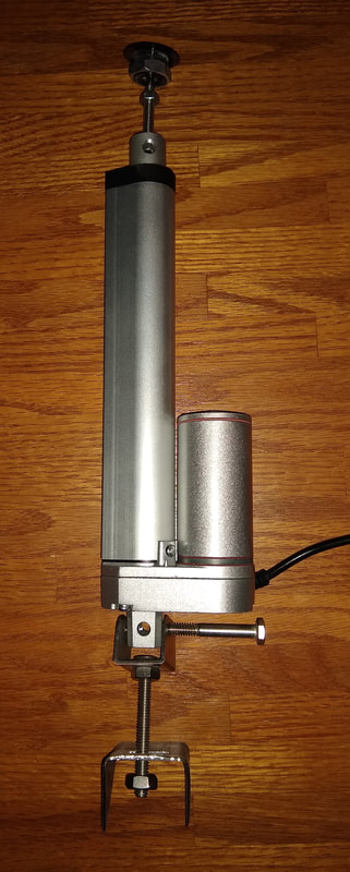
It was during the period since my previous post that the COVID-19 situation became widely known and altered my life and the lives of everyone I know. And while it has made my life less convenient (bad), I have avoided the illness thus far (good) and I have much more time by myself (bad) to work on the Cheetah (good). I have also been forced to use some ingenuity to solve fabrication problems without unnecessarily exposing myself with trips to the hardware store. Incidentally, my home is very unusual in that it is a 20,000+ square foot metal building that was once a private school. It was uninhabitable when I bought it and I spent more than a year turning a portion of it into a living space with two garages and several shop areas. As I did 99% of the work myself, I accumulated a large store of leftover parts and materials that I have the luxury of keeping because of my vast storage space. So when I need something that would have otherwise required a trip to the store, I often find something inhouse that is just what I needed, or can be modifed to work. Such was the case with the parts for the actuator assembly.
One of the two significant tasks that the Ohio shop failed to complete was the "rear shelf" that covers the area from the back of the cockpit to the aft part of the body. The shop gave me some aluminum and some very rough patterns for how it was to be mounted. As I tried to employ their design I discovered a serious shortcoming. As this picture of a similar car (not mine) shows, the cockpit is surrounded by metal plate, but the area behind is completely open to expose the fuel tank, rear suspension and ground below.
One of the two significant tasks that the Ohio shop failed to complete was the "rear shelf" that covers the area from the back of the cockpit to the aft part of the body. The shop gave me some aluminum and some very rough patterns for how it was to be mounted. As I tried to employ their design I discovered a serious shortcoming. As this picture of a similar car (not mine) shows, the cockpit is surrounded by metal plate, but the area behind is completely open to expose the fuel tank, rear suspension and ground below.
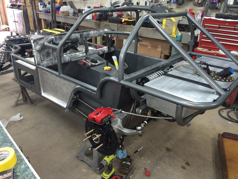
The shop's design for the rear shelf was entirely cosmetic as it hid the tank but did not block vast amounts of air and fuel fumes from entering the cockpit from below. So I discarded their design and fabricated three overlapping aluminum sheets that cover 95% of the ways air might enter from below. The remaining opening are integral to the design of the fiberglass body / wheel wells and will be filled with expanding foam and then covered. The shop's failure to build the rear shelf (bad) resulted in me building one that will do a better job of keeping the cockpit comfortable (good).
The other significant task the Ohio shop failed to complete was installing filler panels between the firewall and the body. The photo below highlights one of the openings with red arrows.
The other significant task the Ohio shop failed to complete was installing filler panels between the firewall and the body. The photo below highlights one of the openings with red arrows.
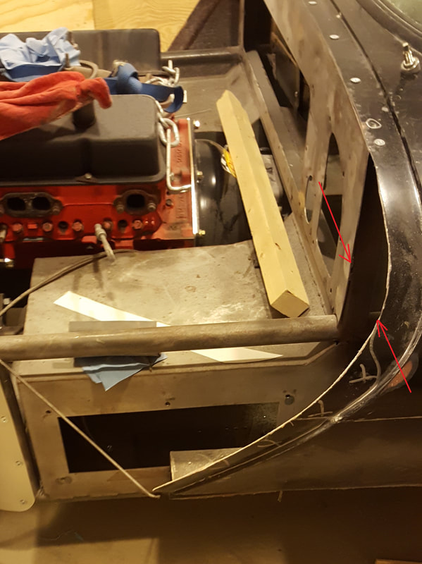
While reviewing their design I discovered two problems similar to the one with the rear shelf. First, the aluminum filler panel sits very close to the exhaust and would transfer heat readily to the frame and interior of the car. Second, there are openings behind the panel that would allow heat from the sidepipes and road air to circulate up and into the cockpit. So I discarded their design and created my own using two panels of flat fiberglass. The first panel will look like their design but will be made of fiberglass covered in insulation. Behind that panel will be a horizontal panel insulated and fit to block any outside air from entering from below. As before, the shop's failure (bad) resulted in a better design (good).
The Ohio shop's most aggregious failure was in not properly fitting the nose before the car was painted. I have made some progress in adjusting the hinge and support rods to make it better, but I am still working to the get the panel fit to my standards. The task would go more quickly if I had a dedicated helper to assist me in removing and replacing the nose for trial and error adjustments. But the COVID-19 situation has made than impractical. So progress in that area is slow (bad). But being in self imposed isolation has allowed me to spend much more time on the Cheetah than I would have otherwise (good). So all-in-all, I am happy with my progress .... and very glad to have this project to keep me occupied during this difficult period.
April 30, 2020
Staying home during the pandemic has encouraged me to work on the Cheetah about three times more than I would have otherwise. And, of course, much of the work has taken three times longer than I imagined it would. So I'm making good progress but not getting ahead of where I thought I would be.
After trying various approaches I have come to accept the fit of the nose after two modifications. First, I tweaked the metal hinges that guide the nose to shift it slightly toward the passenger side. Second, I moved the mounting holes that hold the driver side wing so it would fit better with both the nose and the body.
In an earlier post I mentioned my plan to use two smaller batteries rather than a traditional full size battery. That was just one step along the way to deciding what battery to use. I researched lead acid, AGM, sealed acid and lithium ion batteries along the way. I wanted my solution to meet four goals: 1. Provide ample cranking amps for a 427 cubic inch high compression engine. 2. Provide ample amp-hours for occasions when the battery was carrying most of the electrical load. 3. Fit in the small spaces immediately foward of the footboxes. 4. Be reasonably affordable. .... After many hours of searching I could not find a solution. One option for three AGM motorcycle batteries came with 1/16th of an inch of working before I accepted failure. In the end I went with a large, heavy AGM battery mounted in an open space between the engine and radiator, and fabricated a tray that I welded to the frame.
One of the more interesting tasks I did next was fabricating heat shield panels for the outside of the footboxes. The exhaust headers go directly over and down the outside of each footbox. Without good insulation those metal boxes would become literally like pizza ovens after a long cruise. I considered several commercially available heat shields before deciding to fabricate my own. Each footbox will be clad on the top and two sides with a shield made of sheet of stainless steel over a layer of ceramic cloth and a sheet of aluminum. The stainless steel is a good reflector and poor conductor of heat. The aluminum sheet is there mainly to support the ceramic cloth that is an excellent insulator but somewhat fragile. The bonus is that the stainless steel should look good and keep its looks over time.
Preparing for the next phase I built rolling dollys to hold the body, nose and chassis. A friend helped me move the body and nose to them so I could begin stripping the chassis of the front and rear suspension and everything attached to it. With the chassis stripped I made a list of all the final welding and grinding I needed to finish before blasting and powder coating. I worked through that list and then set to installing rivnuts (i.e., barrel nuts installed with a rivet tool) that would be used to secure panels and components attached to the chassis. When that was done I put a screw or nut in or on every threaded item attached to the chassis. This was to protect the threads and keep debris out of the frame during the blasting and powder coating process.
The actions described in a few words in the above paragraph actually took many days and hours. This is because the decisions about where to weld brackets and mount components took a lot of consideration. I don't want to ruin a freshly powder coated chassis by having to weld something on that should have been done earlier. It is unlikely I thought of every possible issue, but I hope I anticipated most of them.
May 10, 2020
With the chassis ready for powder coating, I loaded it and several more steel parts on to my trailer and carried them to the coater for a quote. His quote was within a few dollars of my back-of-the-envelope estimate so I scheduled the work with him in June.
Another job that required outside help is ceramic coating the exhaust headers and side pipes. The stainless steel looks nice as is, but ceramic coating will help more of the heat exit through the end rather than bake the footboxes and nearby paint. I located a sho9 near Atlanta for the work. But I first needed to do something about the ugly welding job done by the "professional" who had worked on a part of the headers.
As mentioned earlier, the headers were built by a professional shop based on a mocked up set I built from PVC pipe. They did an excellent job that went from the mounting flange to the collector pipe. I decided to make the side pipes from 4" diameter stainless steel pipes intended for large diesel trucks. My challenge was to design and fabricate the portion that connected the 4" collector to the side pipes. To do that I mounted the headers and side pipes where they belonged and used sections of 4" stainless steel elbows to connect them. The final connection was made with V-band clamps so the side pipes could be easily accessed to fine tune the baffles inside. When I had everything where I wanted, I tack welded the collectors, elbows, clamps and side pipes, and took them all to a well regarded "professional" welding shop to have all the final welding done by a TIG welder.
I was sorely disappointed by the welding done on the elbows when I saw it. The shop aplogized, offered some excuses and lowered their price for the work, but it still sucked. I can best describe the work as something I might have done with my MIG welder followed by a lot of time with a grinder. I speculate that after they welded the clamp flanges, their good welders went out on a better paying job and my job was finished by the new guy with the MIG. I decided to seek advice from a real welding professional to see if the welding could be salvaged.
Through a close friend and fellow car guy I was introduced to Scott Miller, a very experienced professional welder who works for the high end aftermarket car company APR in Opelika, Alabama. In a matter of minutes Scott put a real TIG bead over the mess I gave him. Compared to his usual work, he described it as "putting lipstick on a pig." But it did look better AND he discovered several spots where the metal had been ground so thin it would have soon developed leaks if not fixed. I'm very grateful for his help. The exhaust system went to the ceramic coater the next day.
While waiting for work on the chassis to begin, I started work cleaning, prepping and painting parts so they will be ready when final assembly begins. One of those jobs is one I had hoped to avoid, but I've known better since I picked up the car in Ohio. ..... I paid the Ohio shop to paint both the inside and outside of the fiberglass parts. The outside was done in Atomic Orange by a good professional painter. The inside was done in a semi-gloss black by the Ohio shop. The inside of the hand-laid fiberglass pieces is rough so I didn't expect it to look smooth and perfect. I just wanted it to look clean and consistent. It isn't.
The root cause of the problem is that the inside of the car was painted before all the preparation (i.e., sanding) on the outside was done. Dust from the white gelcoat got inside the car and into tiny holes and crevices. Further, the tape line that separated the outside from the inside collected dust leaving a thin white line where the orange and black paints meet. As a result I have to mask off the orange exterior and repaint the interior to cover all the white lines and specks. This is yet another reason I am happy that the Ohio shop is no longer in the business of making cars.
Cleaning and painting are not my favorite activities, so I was happy to work on something a litle different for a while. I had spent many hours researching the ins and outs of positive crankcase ventilation (PCV) systems. These systems capture the combustion gases that escape past the piston rings into the crankcase and can cause oil leaks, contamination of engine oil and environmental pollution. There are numerous ways to address PCV including not having one. (My Shelby Cobra had only a vent but not a PCV.) I knew I wanted a PCV system for the Cheetah but was hampered by my desire to use authentic looking finned aluminum Corvette valve covers from 1963. The problem is that most modern engines use fittings in the valve covers and that was not the case in 1963. Further, newer versions of the small block Chevy engine use one of the fittings in the valve cover as the place where oil can be added to the engine. I would need to address both issues to use the Corvette valve covers.
My solution was based on what many others have already done. I decided to modify both valve covers and the intake manifold to create a PCV system. The left valve cover will have a fitting screwed to the end to allow contaminated air to be sucked out. The end of the fitting will be covered by a baffle to reduce the chance that liquid oil will be sucked out. That fitting will be connected by a hose to a PCV valve screwed into the intake manifold. To do that I selected a popular PCV valve for these applications and drilled and tapped a hole for it in the intake manifold. With the contaminated air side done, I will attach a breather to the other valve cover. This snorkle like device has a foam filter inside to allow outside air to be drawn into the engine as needed. Further, the top and filter can be easily removed so oil can be added to the engine through the breather. Final positiioning of the breather will have to wait until the body is back on the car so I can be sure it does not touch the nose.
June 7, 2020
I hope I am nearing the end of this particular page and ready to start the next page about the final assembly of the Cheetah. The chassis and metal parts are out for powder coating and due back within ten days. The exhaust system has been ceramic coated and looks good. I've repainted the interior surfaces of the nose and body to clean them up and I made a failed attempt at installing headliner on the very small pieces of body that could use it. The problem is there is no easy way to either install the entire awkward piece at once, or do it piecemeal without creating ugly joints. As most of the the upper part of the body is obscured by the tube frame / roll bar, I simply painted it matte black.
A topic that absorbed much of my time and thought is insulating the body and cockpit from damaging heat from the exhaust and engine. I obtained samples of about ten difference heat shields and have decided on a combination that provide the following:
- Good thermal protection in critical areas
- Thin shielding in areas where space is limited
- Looks good where it will be in plain sight
- Not too hard to install
- Durable
Here is my insulation plan organized by type of shielding.
- LizardSkin ceramic spray-on paint
- The entire inside surface of the metal cockpit including the firewall, foot boxes, transmission tunnel, floors and side and back walls
- Aluminized fiberglass fabric with adhesive backing
- The exterior surface of the transmission tunnel
- Interior surfaces of the firewall and foot boxes
- Interior surfaces of the cockpit outer walls
- The nose above the engine area
- Selected fiberglass panels near the exhaust
- Stainless steel - ceramic fabric - aluminum sandwich sheets
- The exterior top, front and outside walls of the foot boxes
- Aluminum sheet metal
- Between the body and side pipes
- Aluminized fiberglass fabric secured with stainless steel ties
- Around frame rails near the exhaust
- Around the steering column near the exhaust
- Around hoses near the exhaust
This may seem like overkill to some, but in a Cheetah the exhaust system wraps around three sides of the metal foot boxes. Without good insulation, they would quickly feel like pizza ovens. Further, the entire cockpit is made with steel sheet metal welded to the frame. So any heat that gets into the metal frame at one point will migrate throught the entire frame and cockpit over time.
June 21, 2020
The chassis and other parts came back from the powder coater sooner than expected. What a rare and pleasant surprise it was to have a vendor exceed my expectations. I immediate set to work sealing all the seams to keep unwanted air and water from the cockpit. When that was done, I masked off all but the cockpit area and sprayed the interior with LizardSkin ceramic heat shield paint. Painting is never fun and this particular material has its own idiosyncracies, but I applied a gallon in a litlle more than an hour. It dried to a lumpy texture that will not matter as it will be beneath carpet.
When the LizardSkin was cured, I remasked the chassis to reveal just the parts of the frame that will be visible in the completed cockpit (e.g, the roll bars). I painted them matte black to reduce any glare they might reflect toward the driver.
With the chassis painting complete, the last thing I needed to do before boltings thing back on to the frame was applying insulation to the bottom side of the transmission tunnel. I spent several hours measuring, marking and cutting out paper patterns to get the aluminized fiberglass fabric just right. I consider the installation of the tunnel insulation as the last preparation step before final assembly begins.
September 12, 2020
Most of the action since I last posted on this page was documented on the main home page. I'm back here to share some details that go somewhat deeper than I want to go on the main page. As was apparent from my earlier comments, the fit of the nose has nagged me ever since I got the car back from Ohio. As I near completion of the build, I was compelled to do something to make it better. The task was made easier by the nose lift actuators I installed earlier. They allow me to lower the nose the last ten inches or so in small increments so I can check the fit. I discovered that one of the fiberglass stringers (a vertical panel that lends strength to the top surface of the nose) was contacting a frame rail during the last few inches of travel. The round frame rail would push the stringer to the side, moving the aft part toward the driver side by about 1/4". I solved that by trimming the stringer and then discovered the entire nose was offset to the driver side by about 3/8".
To address the offset problem I temporarily supported the nose while I removed the large tube that serves as a hinge for the nose. The tube is bolted to the nose and has a pair of arms on each side that line up with extensions on the front of the frame. Pins go through holes in the arms and extensions to tie the nose to the frame and allow it to pivot up. With the tube removed, I cut one arm on each side and rewelded it about 3/8" toward the driver side. After the tube was repainted, I reinstalled it and shifted the nose toward the passenger side by 3/8". I used washers as spacers to fill the enlarged gap between each pair of arms and keep the nose from moving left or right. This approach also gave me the option of fine tuning the position of the nose by moving washers from one side to the other.
Of course the problem with the fit of the nose was not completely fixed. I then discovered the aft portion of the nose was pointed slightly toward the passenger side of the car, making the gap between the nose and body too large on the passenger side and too tight on the nose side. To fix that I agin removed the hinge tube and repositioned the holes in the arms on the passenger side. That meant grinding out the holes on one side and filling in the opposite side with welding. With freshly drilled holes, I reinstalled the tube hinge and declared the fit of the nose to be ...... satisfactory. It's not perfect or great. But I believe it is as good as it can be without a one year delay and another $10K paint job.
September 26, 2020
Having decided to do most of the interior and upholstery work myself, I have been wrestling with how to best deal with edges where components meet. For example, the line where carpet on the vertical side wall meets carpet on the floor is easy. By putting the floor carpet in first, the exposed edge at the floor is covered by the wall carpet that overlaps it. As the edge of the wall carpet is pointed down away from the passenger, neither edge is visible. The line at the top of the wall carpet is an entirely different problem.
There are numerous places with the edge of a cut carpet cannot be hidden by another piece of upholstery. After considering several options I have decided to have the raw egdes bound with professionally sewn carpet binding. I located a local carpet business to do the work and had them tell me the limits of their capabilities. It turns out they cannot easily do inside corners due to the way their sewing machine works. They can do an inside corner but the carpet must be cut nearby and then bonded back together after sewn. When done well, the split is not noticable. I've had three carpet pieces sewn so far and four more will be needed. When complete it will remind me of the carpet in my 1963 Corvette that is also made up of several individual pieces with bound edges.
One challenge that became apparent to me only over the past few months is limiting outside air flow into the cockpit. It may be easier to understand if I compare my Cheetah to the Shelby Cobra replica I used to own. The Cobra had a one piece fiberglass tub that was reinforced with steel where hinges for the doors and hood mounted. As a result, all the fiberglass pieces attached to the body and it was simply bolted to the frame on which it sat. As the tub was a single piece, the only places air could enter from below were in holes cut by the builder.
On the Cheetah each fiberglass piece is individually attached to the chassis. The first problem that creates is aligning the body panels as was described earlier. The second problem is that it leaves many gaps where air can pass. I have worked hard to find and close as many of those gaps as possible, but the cockpit is far from air tight. My hope is that I can keep out enough of the cold air in the winter to give the heater a fighting chance of keeping up. I have little hope that the air conditioner stands a chance on a hot summer day in Alabama. This is particularly true because the side windows cannot be opened or closed while driving. They can only be installed or removed in advance. I realize that sounds very incovenient, but when you consider that the original Cheetahs did not have side windows, its quite a luxury.
